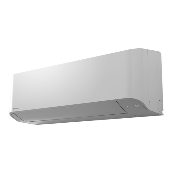

Related Manuals for Toshiba RAV-HM901KRTP Series


Summarization of Contents
Definition of Qualified Installer or Qualified Service Person
Qualifications and Knowledge for Agents
Details the qualifications and knowledge required for installers and service personnel.
Safety and Warning Symbols
Definition of Protective Gear
Outlines the protective gear required for various work tasks.
Meaning of Symbols Displayed on the Unit
Explains the meaning of various symbols displayed on the air conditioner unit.
Unit Warning Indications
Confirmation of Warning Labels
Confirms that warning labels are correctly indicated on the unit.
Safety Precautions
DANGER Statements
Details critical safety warnings related to electrical shock and handling.
General Safety Guidelines
General Warnings
Provides general warnings and mandatory safety procedures for operation.
Refrigerant Handling and Safety
Refrigerant R32 Safety
Details precautions for handling R32 refrigerant, including its properties and risks.
Post-Repair and Installation Checks
Check After Repair
Outlines checks to be performed after repair work is completed.
Check After Reinstallation
Details checks required after relocating the air conditioner unit.
Installation and Relocation Guidelines
Installation Precautions
Provides essential precautions and guidelines for installing the air conditioner.
Relocation Procedures
Details the safe procedure for relocating the air conditioner unit.
Unit Specifications
Model Specifications Overview
Lists specifications like sound pressure level and weight for different models.
Detailed Specifications
High-Wall Type Specifications
Details cooling/heating capacity, electrical characteristics, and dimensions.
Construction Views (External)
Indoor Unit Construction Details
Provides detailed dimensions and external views of the indoor unit.
Refrigerating Cycle Diagram
High Wall Type Single System Diagram
Illustrates refrigerant flow for a single indoor/outdoor unit combination.
Wiring Diagram
Indoor Unit Wiring Diagram
Illustrates the internal wiring connections for the indoor unit.
Electrical Parts Specifications
Name of Electrical Components
Identifies and describes electrical components like fan motor and sensors.
Refrigerant R32 Safety and Handling
Safety During Installation/Servicing (R32)
Details critical safety precautions for R32 refrigerant installation and servicing.
Refrigerant Piping Installation
Covers guidelines for installing refrigerant piping, including materials and joints.
Required Tools for R32 Systems
Tools Exclusive for R32
Lists tools specifically required for R32 systems and their interchangeability.
General Tools
Lists general tools that can also be used for R22 systems.
Refrigerant Recharging Procedure
Steps for Recharging Refrigerant
Provides a step-by-step guide for recharging refrigerant into the system.
Brazing Pipes and Flux Usage
Materials for Brazing
Describes the types of brazing fillers and their suitability.
Flux Requirements and Types
Explains the characteristics and types of flux necessary for brazing.
Brazing Method to Prevent Oxidation
Brazing Procedure with Nitrogen Gas
Details the brazing method using nitrogen gas to prevent oxidation.
Indoor Unit Control Overview
Indoor Controller Block Diagram
Shows the block diagram of the indoor unit control system.
Wired Remote Controller Connection
Illustrates the connection of a wired remote controller to the indoor unit.
Wireless Remote Controller Connection
Connection of Wireless Remote Controller
Explains how to connect the wireless remote controller to the system.
Control Specifications
High-Wall Type Control Specifications
Details control specifications for the high-wall type unit.
Detailed Control Functions
Room Temperature Control
Explains room temperature control methods and settings.
Automatic Capacity and Cooling/Heating Control
Describes automatic capacity and cooling/heating control functions.
Fan Speed and Air Discharge Control
Fan Speed Control
Explains how fan speed is controlled based on various conditions.
Specific Airflow and Preventive Controls
Cool Air Discharge Preventive Control
Details the control for preventing cool air discharge.
Fan Speed Control Details
Provides specific fan speed settings for different modes and models.
Specialized Operation Controls
Freeze and High-Temperature Release Control
Explains controls for freeze prevention and high-temperature release.
Additional Indoor Unit Operations
Louver and HA Control
Details louver control and HA control functions for the indoor unit.
Test Run and Mode Selection
Frequency Fixed Operation (Test Run)
Explains how to perform a frequency-fixed operation test run.
Central Control Mode Selection
Describes how to select modes for central control systems.
Power Saving and Frequency Control
Power-Saving Control
Details the power-saving operation mode and its settings.
Max Frequency Cut Control
Explains the control that limits the maximum operational frequency.
Special Operation Modes
Self-Clean and Auto Restart Operations
Covers self-clean operation and automatic restart after power failure.
Save Operation
Describes the save operation function for preserving settings.
Specialized Heating and Power Operations
8°C Heating Operation
Explains the 8°C heating operation for cold climates.
Hi POWER Operation
Details the Hi POWER operation for increased cooling or heating.
Comfort Sleep Operation
Comfort Sleep Mode Details
Explains the COMFORT SLEEP operation for optimized comfort.
Preset, Quiet, and Sleep Operations
Preset, Quiet, and Sleep Operations
Describes Preset, Quiet, and Sleep operations for user convenience.
Additional Operational Controls
Soft Cooling and Dual Set Point
Covers soft cooling and dual set point (AUTO mode) configurations.
Fan Speed and Draft Prevention
Details fan speed settings and draft prevention control.
Communication and Rotation Controls
Communication Type Setting
Explains how to set the communication type between units.
Rotation and Backup Operation
Describes rotation control and backup operation for multiple units.
Defrost Shift and Rotation Operation Details
Defrost Shift Function
Details the function to shift defrost operation timing.
Power Shift Control
Power Shift Functionality
Explains the power shift control for balancing load in group operations.
Free Cooling Operation
Free Cooling Setup
Describes the setup and conditions for free cooling operation.
Secondary Heating Operation
Secondary Heating Control Modes
Explains the control outlines for secondary heating in Normal and Flip modes.
Indoor Print Circuit Board Details
MCC-1696 PCB Layout
Shows the layout and component locations on the MCC-1696 PCB.
P.C. Board Optional Switch and Connector Specs
P.C. Board Connector Specifications
Lists specifications for optional switches and connectors on the P.C. board.
Troubleshooting Summary
Before Troubleshooting
Lists required tools and initial confirmation points before troubleshooting.
Troubleshooting Procedure
Outlines the procedure for diagnosing and resolving troubles.
Wireless Controller Troubleshooting
Wireless Controller Troubleshooting Procedure
Details the troubleshooting procedure specific to wireless remote controllers.
Troubleshooting: Judgment and Check Codes
Outline of Judgment
Explains how to judge troubles based on lamp indications and check codes.
Troubleshooting: Other than Check Codes
Troubleshooting Without Check Codes
Covers troubleshooting steps for issues not indicated by specific check codes.
Indoor Unit Check Code List
Check Code List for Indoor Units
Provides a list of check codes for indoor unit faults and their meanings.
Diagnostic Function Operation
Indoor Unit Diagnostic Function
Explains the diagnostic function of the indoor unit and its operation modes.
Remote Controller/Central Controller Troubleshooting
Remote Controller/Central Controller Communication Issues
Details troubleshooting for communication problems with controllers and central systems.
Diagnostic Procedures for E01 and E09 Troubles
E01 Trouble Diagnostic Procedure
Provides a diagnostic flowchart for troubleshooting E01 errors.
E09 Trouble Diagnostic Procedure
Provides a diagnostic flowchart for troubleshooting E09 errors.
Diagnostic Procedure for E04 Trouble
E04 Trouble Diagnostic Procedure
Details the diagnostic procedure for resolving E04 errors.
Diagnostic Procedures for E18, E08, L03, L07, L08, and L09 Troubles
E18 Trouble Diagnostic Procedure
Provides a diagnostic flowchart for troubleshooting E18 errors.
E08, L03, L07, L08, L09 Trouble Diagnostics
Covers diagnostic procedures for E08, L03, L07, L08, and L09 errors.
Diagnostic Procedures for L20, L30, and P30 Troubles
L20 Trouble Diagnostic Procedure
Details the diagnostic procedure for L20 errors.
L30 and P30 Trouble Diagnostics
Covers diagnostic procedures for L30 and P30 (Central controller) errors.
Diagnostic Procedure for F10 Trouble
F10 Trouble Diagnostic Procedure
Provides a diagnostic flowchart for troubleshooting F10 errors.
P12 Error Troubleshooting
P12 Error Troubleshooting Steps
Outlines the step-by-step procedure for diagnosing and resolving P12 errors.
Diagnostic Procedures for P19, F02, and F01 Troubles
P19 Trouble Diagnostic Procedure
Details the diagnostic procedure for P19 errors.
F02 and F01 Trouble Diagnostics
Covers diagnostic procedures for F02 (TC sensor) and F01 (TCJ sensor) errors.
Diagnostic Procedure for C06 Trouble
C06 Trouble Diagnostic Procedure (1:1 Model)
Provides a diagnostic flowchart for C06 errors related to the 1:1 model.
Specific Trouble Descriptions
E03, F29, and P31 Trouble Explanations
Explains the causes for E03 (Header unit), F29 (EEPROM), and P31 (Follower unit) troubles.
Temperature Sensor Characteristics
Sensor Resistance Value Characteristics
Provides resistance value characteristics for various temperature sensors.
Service P.C. Board Replacement
Indoor Unit P.C. Board Replacement
Details the procedure for replacing the indoor unit's service P.C. board.
EEPROM Data Handling
Covers reading and writing EEPROM data before and after P.C. board replacement.
EEPROM Data Readout Procedures
Reading EEPROM Data with RBC-ASCU1* Controller
Explains how to read EEPROM data using the RBC-ASCU1* remote controller.
Reading EEPROM Data with RBC-AMTU3* Controller
Explains how to read EEPROM data using the RBC-AMTU3* remote controller.
P.C. Board Replacement Procedures
P.C. Board Replacement Steps
Outlines the steps for replacing the P.C. board for indoor unit servicing.
Single and Group Operation Setup
Details setup procedures for single and group operations after board replacement.
Writing EEPROM Data
Writing EEPROM Data with RBC-ASCU1* Controller
Explains how to write EEPROM data using the RBC-ASCU1* remote controller.
Writing EEPROM Data with RBC-AMTU3* Controller
EEPROM Data Writing Steps (RBC-AMTU3*)
Details the steps for writing EEPROM data using the RBC-AMTU3* remote controller.
Setup at Local Site and Others
Test Run Setup on Remote Controller
Describes how to perform a test run setup using the remote controller.
Specific Setup Procedures
Forced Defrost Setup (Wired Remote)
Explains how to set up forced defrost operation using a wired remote controller.
P.C. Board LED Display Indicators
Details the meaning of LED indicators on the P.C. board.
Function Selection Setup
Function Setup with RBC-ASCU1* Controller
Guides through function selection setup using the RBC-ASCU1* controller.
Function Selection Setup with RBC-AMTU3* Controller
Function Setup Steps (RBC-AMTU3*)
Details the steps for function selection using the RBC-AMTU3* remote controller.
Function Code (DN Code) Table
Function Code Table Overview
Provides a comprehensive table of function codes (DN Codes) and their descriptions.
Address Setup Details
Central Control and Indoor Unit Address Setup
Details setup for central control and indoor unit addresses.
Line and Group Address Setup
Explains the setup procedures for line and group addresses.
Remote Controller Wiring and Setting
2-Remote Controller Control
Details how to operate the unit using two remote controllers.
Setting Remote Controller as Follower
Guides on setting a remote controller as a follower unit.
Wireless Remote Controller A-B Selection
Wireless Remote Controller B Setup
Explains the procedure for setting up the wireless remote controller B.
Remote Controller Monitor Function
Monitor Function for Sensor Data
Describes how to use the monitor function to view sensor data.
Monitoring Data Points
Indoor and Outdoor Unit Data Points
Lists the available indoor and outdoor unit data points for monitoring.
Trouble History and Confirmation
Troubleshooting History Procedure
Details the procedure for checking the troubleshooting history.
Indoor Unit Power-ON Sequence
Power-ON Sequence and Address Judgment
Explains the indoor unit power-ON sequence and automatic address judgment.
1:1 Model Connection Interface Setup
Function and Microprocessor Block Diagram
Describes the function and block diagram of the 1:1 model connection interface.
Wiring Connection for 1:1 Model
Details the wiring connections for the 1:1 model interface.
Wiring and P.C. Board Switch Setup
Wiring Specifications and Cautions
Covers wiring specifications and important cautions for connections.
P.C. Board Switch (SW01) Setup
Explains how to set up the terminator using the P.C. board SW01.
Address Setup Procedures
External View of P.C. Board Assembly
Shows the external view of the P.C. board assembly.
Central Control Address Setup
Details how to set up the central control address number.
Address Setup
Address Setup Procedure
Outlines the procedure for setting unit addresses.
Address Setup and Group Control
Terminology for Address and Group Control
Defines terms used in address setup and group control.
System Configuration Examples
Illustrates different system configurations for address setup.
Group Operation Configurations
Single Group Operation
Describes the configuration for single group operation.
Multiple Groups Operation (Manual)
Explains manual address setting for multiple groups.
Automatic Address Examples
Automatic Address Examples for Group Operation
Shows examples of automatic address setup for group operations.
Manual Address Setup from Remote Controller
Line Address Setup
Guides on setting the line address using the remote controller.
Indoor Unit and Group Address Setup
Indoor Unit Address Setup
Details how to set the indoor unit address.
Group Address Setup
Explains how to set the group address for units.
Maintenance and Check List
Regular Maintenance Schedule
Provides a schedule for regular cleaning and maintenance of units.
How to Replace Main Parts
Air Inlet Grille Replacement
Details the steps for removing and reinstalling the air inlet grille.
Replacing Filters and Front Panel
Air Filter Replacement
Explains how to remove and replace the air filters.
Front Panel Replacement
Details the steps for removing and reinstalling the front panel.
Electric Part Box Assembly Replacement
Electric Part Box Assembly Removal
Guides on removing the electric part box assembly.
Fan Motor and Louver Replacement
Fan Motor Replacement
Details the steps for replacing the fan motor.
Horizontal Louver Replacement
Explains how to remove and reinstall the horizontal louver.
Drain Pan Assembly Replacement
Drain Pan Assembly Removal
Guides on removing and reinstalling the drain pan assembly.
Louver, Bearing, and Fan Replacement
Vertical Louver and Bearing Base Replacement
Details replacement of vertical louver and bearing base.
Cross Flow Fan Replacement
Explains the procedure for replacing the cross flow fan.
Heat Exchanger Replacement
Heat Exchanger (Evaporator) Replacement
Details the steps for removing and reinstalling the heat exchanger.
Microcomputer Replacement
Microcomputer Replacement Procedure
Guides on replacing the microcomputer assembly.
Exploded Views and Parts List
High Wall Type Exploded View
Shows an exploded view of the high wall type air conditioner unit.
Parts List for High Wall Type
Lists all service parts for the high wall type air conditioner.
Electric Parts List
List of Electric Parts
Provides a list of electric parts including PC boards, sensors, and terminals.
Warnings on Refrigerant Leakage
Check of Concentration Limit
Explains the importance of checking concentration limits for refrigerant leakage.
Refrigerant Leakage Notes and Guidelines
Provides important notes and guidelines regarding refrigerant leakage.
Need help?
Do you have a question about the RAV-HM901KRTP Series and is the answer not in the manual?
Questions and answers