Table of Contents
Advertisement
Residential Air Conditioners and Heat Pumps
Using R-22 and Puron® Refrigerant
Application Guideline and Service Manual
UNIT IDENTIFICATION . . . . . . . . . . . . . . . . . . . . . . . . . . . . . . . . . 3
SAFETY CONSIDERATIONS . . . . . . . . . . . . . . . . . . . . . . . . . . . . . 4
INTRODUCTION . . . . . . . . . . . . . . . . . . . . . . . . . . . . . . . . . . . . . . . 4
INSTALLATION GUIDELINE. . . . . . . . . . . . . . . . . . . . . . . . . . . . . 4
Residential New Construction . . . . . . . . . . . . . . . . . . . . . . . . . . . . 4
Add-On Replacement (Retrofit) - R22 to Puron . . . . . . . . . . . . . . 4
Seacoast . . . . . . . . . . . . . . . . . . . . . . . . . . . . . . . . . . . . . . . . . . . . . 4
Accessories . . . . . . . . . . . . . . . . . . . . . . . . . . . . . . . . . . . . . . . . . . . . . 5
ACCESSORY DESCRIPTIONS . . . . . . . . . . . . . . . . . . . . . . . . . . . . 6
LOW-AMBIENT COOLING GUIDELINE . . . . . . . . . . . . . . . . . . . 7
LONG LINE GUIDELINE. . . . . . . . . . . . . . . . . . . . . . . . . . . . . . . . . 8
CABINET ASSEMBLY. . . . . . . . . . . . . . . . . . . . . . . . . . . . . . . . . . . 8
Basic Cabinet Designs . . . . . . . . . . . . . . . . . . . . . . . . . . . . . . . . . . 8
Labeling . . . . . . . . . . . . . . . . . . . . . . . . . . . . . . . . . . . . . . . . . . . . 11
ELECTRICAL . . . . . . . . . . . . . . . . . . . . . . . . . . . . . . . . . . . . . . . . . 12
Aluminum Wire . . . . . . . . . . . . . . . . . . . . . . . . . . . . . . . . . . . . . . 12
Contactor . . . . . . . . . . . . . . . . . . . . . . . . . . . . . . . . . . . . . . . . . . . 12
Capacitor . . . . . . . . . . . . . . . . . . . . . . . . . . . . . . . . . . . . . . . . . . . 12
Cycle Protector. . . . . . . . . . . . . . . . . . . . . . . . . . . . . . . . . . . . . . . 13
Crankcase Heater . . . . . . . . . . . . . . . . . . . . . . . . . . . . . . . . . . . . . 13
Time-Delay Relay (TDR) . . . . . . . . . . . . . . . . . . . . . . . . . . . . . . 14
Pressure Switches. . . . . . . . . . . . . . . . . . . . . . . . . . . . . . . . . . . . . 14
Defrost Thermostat . . . . . . . . . . . . . . . . . . . . . . . . . . . . . . . . . . . 15
Defrost Control Boards . . . . . . . . . . . . . . . . . . . . . . . . . . . . . . . . 15
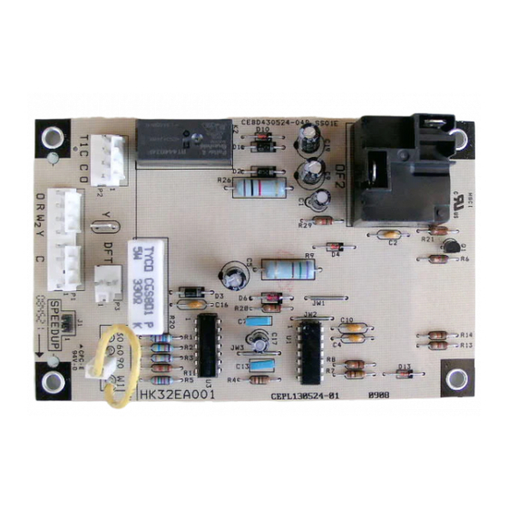
HK32EA001/007 DEFROST CONTROL. . . . . . . . . . . . . . . . . . 15
HK32EA009 DEFROST CONTROL . . . . . . . . . . . . . . . . . . . . . 17
HK32EA003 / 008 DEFROST CONTROL. . . . . . . . . . . . . . . . . 17
Troubleshooting (HK32EA003/008) . . . . . . . . . . . . . . . . . . . . . 18
HK32EA008 DEFROST CONTROL . . . . . . . . . . . . . . . . . . . . . 18
Quiet Shift-2 (non-communicating). . . . . . . . . . . . . . . . . . . . . . . 18
HK32EA010 DEFROST CONTROL . . . . . . . . . . . . . . . . . . . . . 18
HK32EA011 DEFROST CONTROL . . . . . . . . . . . . . . . . . . . . . 18
Outdoor Fan Motors . . . . . . . . . . . . . . . . . . . . . . . . . . . . . . . . . . . . . 20
ECM Fan Motor . . . . . . . . . . . . . . . . . . . . . . . . . . . . . . . . . . . . . . 20
PSC Fan Motor. . . . . . . . . . . . . . . . . . . . . . . . . . . . . . . . . . . . . . . 20
Compressor Plug . . . . . . . . . . . . . . . . . . . . . . . . . . . . . . . . . . . . . 20
Low-Voltage Terminals . . . . . . . . . . . . . . . . . . . . . . . . . . . . . . . . 20
COPELAND SCROLL COMPRESSOR. . . . . . . . . . . . . . . . . . . 20
LG SCROLL COMPRESSOR. . . . . . . . . . . . . . . . . . . . . . . . . . . 21
Characteristics of the LG Scroll Compressor: . . . . . . . . . . . . . . . 21
COMPRESSOR TROUBLESHOOTING . . . . . . . . . . . . . . . . . . 22
Compressor Failures . . . . . . . . . . . . . . . . . . . . . . . . . . . . . . . . . . 22
Mechanical Failures . . . . . . . . . . . . . . . . . . . . . . . . . . . . . . . . . . . 22
Noisy Compressor . . . . . . . . . . . . . . . . . . . . . . . . . . . . . . . . . . . . 23
Electrical Failures . . . . . . . . . . . . . . . . . . . . . . . . . . . . . . . . . . . . 24
REFRIGERATION SYSTEM . . . . . . . . . . . . . . . . . . . . . . . . . . . . . 25
Refrigerant . . . . . . . . . . . . . . . . . . . . . . . . . . . . . . . . . . . . . . . . . . 25
Servicing Systems on Roofs With Synthetic Materials . . . . . . . . 25
Brazing . . . . . . . . . . . . . . . . . . . . . . . . . . . . . . . . . . . . . . . . . . . . . 26
Aluminum Brazing. . . . . . . . . . . . . . . . . . . . . . . . . . . . . . . . . . . . 26
Service Valves and Pumpdown . . . . . . . . . . . . . . . . . . . . . . . . . . 26
Liquid Line Filter Drier . . . . . . . . . . . . . . . . . . . . . . . . . . . . . . . . 29
Suction Line Filter Drier . . . . . . . . . . . . . . . . . . . . . . . . . . . . . . . 29
Accumulator. . . . . . . . . . . . . . . . . . . . . . . . . . . . . . . . . . . . . . . . . 30
Thermostatic Expansion Valve (TXV) . . . . . . . . . . . . . . . . . . . . 31
Make Piping Connections. . . . . . . . . . . . . . . . . . . . . . . . . . . . . . . . . 32
REFRIGERATION SYSTEM REPAIR. . . . . . . . . . . . . . . . . . . . . . 33
Leak Detection . . . . . . . . . . . . . . . . . . . . . . . . . . . . . . . . . . . . . . . 33
Coil Removal . . . . . . . . . . . . . . . . . . . . . . . . . . . . . . . . . . . . . . . . 33
Aluminum Coil Removal. . . . . . . . . . . . . . . . . . . . . . . . . . . . . . . 34
Compressor Removal and Replacement . . . . . . . . . . . . . . . . . . . 35
System Clean-Up After Burnout . . . . . . . . . . . . . . . . . . . . . . . . . 35
Evacuation . . . . . . . . . . . . . . . . . . . . . . . . . . . . . . . . . . . . . . . . . . 35
Check Charge . . . . . . . . . . . . . . . . . . . . . . . . . . . . . . . . . . . . . . . . . . 36
TROUBLESHOOTING with SUPERHEAT . . . . . . . . . . . . . . . . . . 37
quence of Operation . . . . . . . . . . . . . . . . . . . . . . . . . . . . . . . . . . . . . 47
Sequence of Operation. . . . . . . . . . . . . . . . . . . . . . . . . . . . . . . . . 47
DEFROST . . . . . . . . . . . . . . . . . . . . . . . . . . . . . . . . . . . . . . . . . . 48
QUIET SHIFT-2 . . . . . . . . . . . . . . . . . . . . . . . . . . . . . . . . . . . . . 48
LIQUID LINE SOLENOID ACCESSORY . . . . . . . . . . . . . . . . 49
MAJOR COMPONENTS . . . . . . . . . . . . . . . . . . . . . . . . . . . . . . 49
TROUBLESHOOTING . . . . . . . . . . . . . . . . . . . . . . . . . . . . . . . . . . 49
Systems Communication Failure . . . . . . . . . . . . . . . . . . . . . . . . . 49
Pressure Switch Protection . . . . . . . . . . . . . . . . . . . . . . . . . . . . . 49
Control Fault . . . . . . . . . . . . . . . . . . . . . . . . . . . . . . . . . . . . . . . . 49
24V Brown Out Protection . . . . . . . . . . . . . . . . . . . . . . . . . . . . . 49
Compressor Voltage Sensing. . . . . . . . . . . . . . . . . . . . . . . . . . . . 49
or Loss of 230V Power . . . . . . . . . . . . . . . . . . . . . . . . . . . . . . . . 49
Contactor Shorted Detection . . . . . . . . . . . . . . . . . . . . . . . . . . . . 50
No 230V at Compressor. . . . . . . . . . . . . . . . . . . . . . . . . . . . . . . . 50
Temperature Thermistors. . . . . . . . . . . . . . . . . . . . . . . . . . . . . . . 50
Thermistor Sensor Comparison . . . . . . . . . . . . . . . . . . . . . . . . . . 50
Failed Thermistor Default Operation. . . . . . . . . . . . . . . . . . . . . . 50
TWO-STAGE 286B/289B 180B/187B . . . . . . . . . . . . . . . . . . . . . . 52
Application Guidelines . . . . . . . . . . . . . . . . . . . . . . . . . . . . . . . . 52
Model Plug. . . . . . . . . . . . . . . . . . . . . . . . . . . . . . . . . . . . . . . . . . 52
nicating (Non-Evolution) Thermostats . . . . . . . . . . . . . . . . . . . . 53
Airflow Selection for FV4 Fan Coils for 180B, 187B, 286B, 289B Us-
ing Non-Communicating (Non-Evolution) Thermostats. . . . . . . 53
GENERAL INFORMATION. . . . . . . . . . . . . . . . . . . . . . . . . . . . . . 53
Low Ambient Cooling . . . . . . . . . . . . . . . . . . . . . . . . . . . . . . . . . 53
Defrost . . . . . . . . . . . . . . . . . . . . . . . . . . . . . . . . . . . . . . . . . . . . . 53
Quiet Shift . . . . . . . . . . . . . . . . . . . . . . . . . . . . . . . . . . . . . . . . . . 54
(part # HK38EA016, HK38EA022, HK38EA023) . . . . . . . . . . . 54
Liquid-Line Solenoid Accessory . . . . . . . . . . . . . . . . . . . . . . . . . 54
Check Charge . . . . . . . . . . . . . . . . . . . . . . . . . . . . . . . . . . . . . . . . . . 54
Heating Check Chart Procedure. . . . . . . . . . . . . . . . . . . . . . . . . . 54
55
Cooling and Heating Operation . . . . . . . . . . . . . . . . . . . . . . . . . . 55
Advertisement
Table of Contents
Troubleshooting

Related Manuals for Bryant Legacy


Summarization of Contents
UNIT IDENTIFICATION
Air Conditioner and Heat Pump Model Number Nomenclature
Explains how to identify model numbers by code.
Serial Number Nomenclature
Details the components of the unit's serial number.
SAFETY CONSIDERATIONS
UNIT OPERATION AND SAFETY HAZARD
Outlines potential dangers during unit operation and service.
INSTALLATION GUIDELINE
Residential New Construction
Specifies requirements for new residential installations.
Add-On Replacement (Retrofit) - R22 to Puron
Details specifications for replacing R22 systems with Puron.
Seacoast
Describes features for units in coastal environments.
ACCESSORIES
Required Field-Installed Accessories for Air Conditioners
Lists accessories needed for AC units based on application.
Required Field-Installed Accessories for Heat Pumps
Lists accessories needed for heat pumps based on application.
ACCESSORY DESCRIPTIONS
Crankcase Heater
Describes the function and usage of a crankcase heater.
Evaporator Freeze Thermostat
Explains the evaporator freeze thermostat's role in preventing coil freezing.
Isolation Relay
Describes the isolation relay used in heat pumps with low ambient kits.
Low-Ambient Pressure Switch
Details the low-ambient pressure switch for condenser fan speed control.
Outdoor Air Temperature Sensor
Explains the function of the outdoor air temperature sensor.
Thermostatic Expansion Valve (TXV)
Describes the TXV's function in metering refrigerant flow.
Time-Delay Relay
Explains the function of the time-delay relay for indoor blower operation.
Wind Baffle
Describes the use of wind baffles to prevent abnormal control operation.
Winter Start Control
Explains the winter start control for AC units in low ambient cooling.
CABINET ASSEMBLY
Basic Cabinet Designs
Illustrates and describes the three basic cabinet designs for units.
ACCESS COMPRESSOR OR OTHER INTERNAL CABINET COMPONENTS
Remove Top Cover - Mid-Tier / Deluxe
Provides steps for removing the top cover on Mid-Tier/Deluxe units.
Remove Fan Motor Assembly - Mid-Tier / Deluxe
Details the procedure for removing the fan motor assembly on these units.
Control Box Cover-Base Products
Describes the control box cover for base product models.
Remove Top Cover-Base Products
Steps for removing the top cover on base product models.
Remove Fan Motor Assembly-Base Products
Procedure for removing the fan motor assembly on base product models.
ELECTRICAL
Aluminum Wire
Guidelines for using aluminum wire in branch circuits and connections.
Contactor
Explains the function and troubleshooting of contactors.
Capacitor
Describes the role and testing of capacitors in single-phase motors.
Cycle Protector
Details the cycle protector's function in preventing compressor short cycling.
Crankcase Heater
Explains the crankcase heater's purpose in keeping compressor oil warm.
Time-Delay Relay (TDR)
Describes the TDR's function in keeping the indoor blower running post-cycle.
Pressure Switches
Explains the function of Puron system pressure switches.
High-Pressure Switch (AC & HP)
Details the high-pressure switch's role in protecting the condenser coil.
Loss of Charge Switch (HP Only)
Explains the loss of charge switch for heat pumps.
Defrost Thermostat
Check Defrost Thermostat
Provides instructions for checking the defrost thermostat's operation.
Defrost Control Boards
HK32EA001/007 DEFROST CONTROL
Describes the HK32EA001/007 defrost control board for Legacy Series.
Cooling Sequence of Operation (HK32EA001/007)
Explains the cooling sequence for the HK32EA001/007 control.
Heating Sequence of Operation (KH32EA001)
Explains the heating sequence for the HK32EA001 control.
Defrost Sequence (HK32EA001/007)
Details the defrost sequence for the HK32EA001/007 control.
Defrost Speedup
Describes how to initiate a forced defrost cycle using speedup pins.
If unit will not defrost
Troubleshooting steps when the unit fails to initiate defrost.
To fully troubleshoot defrost thermostat and control function (HK32EA001/007)
Comprehensive troubleshooting for defrost thermostat and control.
HK32EA009 DEFROST CONTROL
Details the HK32EA009 defrost control for units with ECM outdoor motors.
HK32EA003/008 DEFROST CONTROL
Describes the HK32EA003/008 defrost control for Preferred Series heat pumps.
System function and Sequence of operation (HK32EA003/008)
Explains the system functions and sequences for the HK32EA003/008 control.
Cooling
Details the cooling sequence of operation for the control.
Heating
Details the heating sequence of operation for the control.
Defrost Sequence
Explains the defrost sequence timing and termination for the control.
Deluxe Defrost Speedup
Describes the deluxe defrost speedup feature for forced defrost initiation.
Troubleshooting (HK32EA003/008)
Troubleshooting steps for the HK32EA003/008 defrost control.
HK32EA008 DEFROST CONTROL
Details the HK32EA008 defrost control for non-communicating Preferred Series.
Quiet Shift-2 (non-communicating)
Explains the Quiet Shift-2 feature for reducing defrost-related noise.
HK32EA010 DEFROST CONTROL
Details the HK32EA010 defrost control for units with ECM outdoor motors.
HK32EA011 DEFROST CONTROL
Details the HK32EA011 defrost control for Legacy Series with aluminum coils.
Outdoor Fan Motors
ECM Fan Motor
Describes ECM fan motor characteristics and troubleshooting.
PSC Fan Motor
Explains the PSC fan motor and its electrical checks.
COPELAND SCROLL COMPRESSOR
Scroll Gas Flow
Illustrates and describes the scroll compressor's gas flow.
LG SCROLL COMPRESSOR
Characteristics of the LG Scroll Compressor
Details the LG scroll compressor's unique characteristics and features.
Internal Motor Overload Protection (OLP)
Explains the OLP system for protecting the motor from overloads.
Vacuum protection device
Describes the vacuum protection feature to prevent internal damage.
Internal Pressure Relief (IPR)
Explains the IPR valve's function to relieve high internal pressure.
Quiet Shut Down Device
Details the quiet shut down device for minimizing noise.
Discharge Temperature Protection
Explains discharge temperature protection to prevent overheating.
COMPRESSOR TROUBLESHOOTING
Compressor Failures
Categorizes compressor failures into mechanical and electrical types.
Locked Rotor
Describes the locked rotor failure mode and its diagnosis.
Runs, Does Not Pump
Explains the 'runs but does not pump' failure mode and its causes.
COMPRESSOR TROUBLESHOOTING
Electrical Failures
Focuses on diagnosing electrical issues causing compressor failure.
Open Circuit
Details how to test for open circuits in compressor windings.
Short Circuit
Explains how to test for short circuits within compressor windings.
Ground Circuit
Describes how to test for a direct short to ground in compressor windings.
REFRIGERATION SYSTEM
Refrigerant
Provides critical information about Puron refrigerant and system safety.
SERVICING SYSTEMS ON ROOFS WITH SYNTHETIC MATERIALS
Synthetic Roof Precautionary Procedure
Outlines steps to protect roofing materials from compressor oil.
BRAZING
Aluminum Brazing
Provides instructions and considerations for brazing aluminum coils.
SERVICE VALVES AND PUMPDOWN
Heating Piston (AccuRater®) - Heat Pumps Only
Details the Accurater piston's function in heat pump heating mode.
LIQUID LINE FILTER DRIER
Install Liquid-line Filter Drier Indoor - AC
Instructions for installing the liquid line filter drier on AC units.
Install Liquid-line Filter Drier Indoor - HP
Instructions for installing the liquid line filter drier on heat pumps.
THERMOSTATIC EXPANSION VALVE (TXV)
TXV Operation
Explains how the TXV operates to maintain preset superheat.
Install TXV
Provides guidelines for installing the TXV correctly.
Installing TXV in Place of Piston in a Rated Indoor Coil (pre-2006)
Steps for replacing a piston with a TXV in older indoor coils.
THERMOSTATIC EXPANSION VALVE (TXV)
Replacing TXV on Indoor Coil (post-2006)
Instructions for replacing a TXV in newer indoor coils.
Make Piping Connections
Details important considerations for making refrigerant piping connections.
REFRIGERATION SYSTEM REPAIR
Leak Detection
Methods and tools for detecting refrigerant leaks in the system.
EVACUATION
Deep Vacuum Method
Explains the deep vacuum method for system evacuation.
EVACUATION
Triple Evacuation Method
Describes the triple evacuation method for system drying.
TROUBLESHOOTING WITH SUPERHEAT
Basic Diagnostics
Initial checks for diagnosing superheat issues in TXV systems.
Low Superheat with Normal or Low Suction Pressure
Troubleshooting steps for low superheat with normal/low suction pressure.
Low Superheat with High Suction Pressure
Troubleshooting steps for low superheat with high suction pressure.
High Superheat with Normal or Low Pressure
Troubleshooting steps for high superheat with normal/low pressure.
TROUBLESHOOTING WITH SUPERHEAT
Hunting Superheat
Addresses hunting superheat issues, typically an application problem.
Pseudo Evaporator Superheat Instructions
Provides instructions for calculating evaporator superheat using available data.
TROUBLESHOOTING WITH SUPERHEAT
Example 1
A detailed example of checking charge and superheat.
TROUBLESHOOTING WITH SUPERHEAT
Example 2
A detailed example of performing Pseudo Evaporator Superheat check.
Single-Stage Communicating Heat Pump System Functions and Sequence of Operation
Sequence of Operation
Overview of the control's sequence of operation for cooling and heating.
Cooling & Heating Operation
Details the sequence of operations for cooling and heating modes.
Communication and Status Function Lights For Evolution Control only, Green communications (COMM) Light
Explains the green COMM light for indicating communication status.
Amber Status Light
Describes the amber status light for operation modes and fault codes.
Outdoor Fan Motor Operation
Explains when the outdoor fan motor operates and its delays.
Time Delays
Lists and describes the various time delays in the unit's operation.
Crankcase Heater Operation
Explains the operation of the crankcase heater during off cycles.
Single-Stage Communicating Heat Pump System Functions and Sequence of Operation
Utility Interface
Describes the utility interface for interrupting compressor operation.
Low Ambient Cooling
Details requirements and operation for low ambient cooling.
Standard Thermostat low ambient cooling mode
Explains requirements for low ambient cooling with standard thermostats.
DEFROST
Covers defrost control intervals, auto defrost, and defrost hold.
Forced Defrost
Explains how to initiate a forced defrost cycle manually or via UI.
QUIET SHIFT-2
Describes the Quiet Shift-2 feature for reducing defrost noise.
Single-Stage Communicating Heat Pump System Functions and Sequence of Operation
LIQUID LINE SOLENOID ACCESSORY
Explains the liquid line solenoid's role in controlling refrigerant migration.
MAJOR COMPONENTS
Lists the major components controlled by the outdoor unit control board.
Control Board
Details the functions controlled by the heat pump control board.
Field Connections
Explains field wiring connections for Evolution and standard thermostats.
TROUBLESHOOTING
Provides guidance for diagnosing system faults and errors.
Systems Communication Failure
Describes troubleshooting steps for lost communication with the UI.
Model Plug
Explains the importance and function of the model plug.
Pressure Switch Protection
Details how pressure switches protect the unit operation.
Control Fault
Describes troubleshooting for a failed outdoor unit control board.
24V Brown Out Protection
Explains the 24V brown out protection feature and its voltage limits.
Compressor Voltage Sensing
Describes how the control monitors compressor voltage status.
Compressor Thermal Cutout or Loss of 230V Power
Addresses issues related to compressor thermal cutout or loss of power.
TROUBLESHOOTING
Contactor Shorted Detection
Diagnoses a contactor stuck closed or a wiring error.
No 230V at Compressor
Troubleshoots lack of 230V at the compressor due to open contactor or wiring.
Temperature Thermistors
Thermistor Sensor Comparison
Explains how the control compares outdoor and coil thermistor readings.
Failed Thermistor Default Operation
Describes default operations when thermistors fail.
Status Codes
Explains how to interpret status codes flashed by the amber status light.
TWO-STAGE 286B/289B 180B/187B
Application Guidelines
Provides application guidelines for two-stage units with Puron refrigerant.
Model Plug
Explains the function and importance of the model plug for unit identification.
TWO-STAGE 286B/289B 180B/187B
Airflow Selections for 187B / 286B / 180B/289B Using Non-Communicating (Non-Evolution) Thermostats
Guidance on selecting airflows for units with non-communicating thermostats.
Airflow Selection for 58CVA/58MVB Furnaces
Details airflow selection for 58CVA/58MVB furnaces.
Airflow Selection for FV4 Fan Coils for 180B, 187B, 286B, 289B Using Non-Communicating (Non-Evolution) Thermostats
Instructions for selecting airflows for FV4 fan coils with non-communicating thermostats.
GENERAL INFORMATION
Provides general information on unit operation and features.
Low Ambient Cooling
Discusses low ambient cooling requirements and operation modes.
Evolution Controlled low ambient cooling
Explains low ambient cooling capabilities with Evolution control.
Defrost
Details defrost control options and operation for two-stage units.
GENERAL INFORMATION
Defrost
Continues discussion on defrost control options and operation.
Defrost Hold
Explains the defrost hold feature for non-communicating systems.
Forced Defrost
Describes how to initiate a forced defrost cycle manually or via UI.
Quiet Shift
Explains the Quiet Shift feature for reducing defrost-related noise.
Quiet Shift-2 (communicating models)
Details the Quiet Shift-2 feature for communicating systems.
Liquid-Line Solenoid Accessory
Explains the liquid line solenoid's role in controlling refrigerant migration.
Check Charge
Provides guidance on checking and adjusting refrigerant charge.
Heating Check Chart Procedure
Outlines the procedure for checking system operation during heating.
System Functions and Sequence Of Operation (286B/89B/180B/187B)
Cooling and Heating Operation
Details the cooling and heating operation sequence for two-stage units.
Communication and Status Function Lights For Evolution Control only, Green communications (COMM) Light
Explains the green COMM light for indicating communication status.
Amber Status Light
Describes the amber status light for operation modes and fault codes.
Utility Interface With Evolution Control
Describes the utility interface for interrupting compressor operation.
Compressor Operation
Explains the operation of the two-stage scroll compressor.
Fan Motor
ECM Fan Motor Troubleshooting
Troubleshooting steps for ECM fan motor failures.
Time Delays
Lists and describes the various time delays in the unit's operation.
Thermistors
Outdoor Ambient Thermistor
Explains the function of the outdoor ambient air thermistor.
Outdoor Coil Thermistor (OCT)
Describes the outdoor coil thermistor's role in temperature sensing.
Thermistor Curve
Provides a chart of thermistor resistance values versus temperature.
Control Box
Contactor And Capacitor
Discusses contactors, capacitors, and incoming power connections.
Incoming Power
Details the connection and grounding of incoming power.
TROUBLESHOOTING
Troubleshooting circuit board
Guidance on troubleshooting the unit's control board.
Systems Communication Failure
Steps for diagnosing communication failures with the user interface.
Model Plug
Explains the function and importance of the model plug.
Pressure Switch Protection
Details how pressure switches protect the unit operation.
Control Fault
Describes troubleshooting for a failed outdoor unit control board.
Brown-Out Protection
Explains the 24V brown out protection feature and its voltage limits.
TROUBLESHOOTING
230v Brown-Out Protection Defeated
Explains how to defeat the brownout feature if severe noisy power conditions exist.
230V Line (Power Disconnect) Detection
Troubleshoots lack of 230V at the compressor contactor.
Compressor Voltage Sensing
Describes how the control monitors compressor voltage status.
Contactor Shorted Detection
Diagnoses a contactor stuck closed or a wiring error.
Compressor Thermal Cutout
Addresses issues related to compressor thermal cutout or loss of power.
Low or High Contactor Open/No 230V at Compressor Contractor
Troubleshoots open contactors or lack of 230V to the compressor.
Troubleshooting units for proper switching between low & high stages
Steps to troubleshoot proper switching between low and high stages.
Unloader Test Procedure
Details how to test the compressor unloader mechanism for proper operation.
Temperature Thermistors
Thermistor Sensor Comparison
Explains how the control compares outdoor and coil thermistor readings.
Failed Thermistor Default Operation
Describes default operations when thermistors fail.
Status Codes
Explains how to interpret status codes flashed by the amber status light.
Two Stage Non-Communicating
Operating Ambient
Details the operating ambient temperature ranges for cooling.
Airflow Selections (ECM Furnaces)
Guidance on selecting airflows for ECM furnaces.
Airflow Selection for 58CVA/58MVB Furnaces
Details airflow selection for 58CVA/58MVB furnaces.
Airflow Selection for FV4 Fan Coils for 180B, 187B, 286B, 289B Using Non-Communicating (Non-Evolution) Thermostats
Instructions for selecting airflows for FV4 fan coils with non-communicating thermostats.
Airflow Selection for Variable Speed Furnaces (non-communicating)
Details airflow selection for variable speed furnaces.
Airflow Selection for FV4C Fan Coils (non-communicating)
Instructions for selecting airflows for FV4C fan coils.
Airflow Selection for FZ4A Fan Coils (non-communicating)
Details airflow selection for FZ4A fan coils.
System Functions and Sequence Of Operation (286B/89B/180B/187B)
Cooling and Heating Operation
Details the cooling and heating operation sequence for two-stage units.
Communication and Status Function Lights For Evolution Control only, Green communications (COMM) Light
Explains the green COMM light for indicating communication status.
Amber Status Light
Describes the amber status light for operation modes and fault codes.
Utility Interface With Evolution Control
Describes the utility interface for interrupting compressor operation.
Compressor Operation
Explains the operation of the two-stage scroll compressor.
Fan Motor
ECM Fan Motor Troubleshooting
Troubleshooting steps for ECM fan motor failures.
Time Delays
Lists and describes the various time delays in the unit's operation.
CARE AND MAINTENANCE
Desert and Seacoast Locations
Special considerations for installation and maintenance in harsh environments.
Maintenance in desert and seacoast locations
Specific maintenance tasks for units in desert and seacoast environments.
Cleaning Coil
Provides instructions for cleaning the unit's coil effectively.
Cleaning Outdoor Fan Motor and Blade
Details the process for cleaning the outdoor fan motor and blade.
Need help?
Do you have a question about the Legacy and is the answer not in the manual?
Questions and answers