Bryant Legacy 574D----A Installation Instructions Manual
13 seer single-packaged air conditioner and gas furnace system with puron (r-410a) refrigerant single and three phase 2-5 nominal tons (sizes 24-60)
Hide thumbs
Also See for Legacy 574D----A:
- Owner's information manual (10 pages) ,
- Product data (57 pages) ,
- Installation instructions manual (28 pages)
Table of Contents
Advertisement
574D- -- -A
LEGACYt 13 SEER SINGLE- -PACKAGED AIR CONDITIONER AND
GAS FURNACE SYSTEM WITH PURONR (R- -410A) REFRIGERANT
SINGLE AND THREE PHASE
2- -5 NOMINAL TONS (SIZES 24- -60)
NOTE:
Read the entire instruction manual before starting the
installation.
NOTE:
Installer: Make sure the Owner's Manual and Service
Instructions are left with the unit after installation.
TABLE OF CONTENTS
. . . . . . . . . . . . . . . . . . . . . . . . . . . . . . . . . . .
. . . . . . . . . . . . . . . . . . . . . . . . . . . . . . . . . .
. . . . . . . . . . . . . . . . . . . . . . . . . . . . . . . . . . . .
. . . . . . . . . . . . . . . . . . . . . . . . . . . . . . . . .
. . . . . . . . . . . . . . . . . . . . . . . . . . . . . . .
. . . . . . . . . . . . . . . . . . . . . . . . . . . . . . . . . . . . . .
. . . . . . . . . . . . . . . . . . . . . . . . . . . . . . . . . . . . .
. . . . . . . . . . . . . . . . . . . . . . . . . . . .
. . . . . . . . . . . . . . . . . . . . . . . . . . . . . . . . .
. . . . . . . . . . . . . . . . . . . . . . . . . . . . . . . . .
. . . . . . . . . . . . . . . . . . . . . . . . . . . . . . . . . . . . . .
. . . . . . . . . . . . . . . . . . . . . . . . . . . . . . . . . .
. . . . . . . . . . . . . . . . . . . . . . . . . . . . . . . . . . .
. . . . . . . . . . . . . . . . . . . . . . . . . . . . . . . . . .
. . . . . . . . . . . . . . . . . . . . . . . . . . . .
. . . . . . . . . . . . . . . . . . . . . . . . . . . . . . . . . . . . .
. . . . . . . . . . . . . . . . . . . . . . . . . . . . .
. . . . . . . . . . . . . . . . . . . . . . . . . . .
. . . . . . . . . . . . . . . . . . . . . . . . . . . . . . . . . . .
. . . . . . . . . . . . . . . . . . . . . . . . . . . . . . . . . . . . .
. . . . . . . . . . . . . . . . . . . . . . . . . . .
. . . . . . . . . . . . . . . . . . . . . . . . . . . . . . . .
. . . . . . . . . . . . . . . . . . . . . . . . . . . . . . . .
. . . . . . . . . . . . . . . . . . . . . . . . . . . . .
. . . . . . . . . . . . . . . . . . . . . . . . . . . . . . .
. . . . . . . . . . . . . . . . . . . . . . . . . . . . . . . . .
. . . . . . . . . . . . . . . . . . . . . . . . . . . . . . . . .
. . . . . . . . . . . . . . . . . . . . . . . . . . . . . . . .
. . . . . . . . . . . . . . . . . . . . . . . . . . . . . . . . . . . . . .
Installation Instructions
. . . . . . . . . . . . . . . . . . . . . . . . .
. . . . . . . . . . . . . . . . .
. . . . . . . . . . . . . . . . . . . . . . . . . . .
. . . . . . . . . . . . . . . . . . . . . . . .
. . . . . . . . . . . . . . . . . . . . . . . .
. . . . . . . . . . . . . .
. . . . . . . . . . . . . . . . . . . . . . .
. . . . . . . . . . . . . . . . . . . . . . . . . .
. . . . . . . . . . . . . . . . . . . . . . . . .
. . . . . . . . . . . . . . . .
. . . . . . . . . . . . . . . . . . . . . .
. . . . . . . . . . . . . . . . . . . . .
. . . . . . . . . . . . . . . .
. . . . . . . . . . . . . . . .
. . . . . . . . . . . .
. . . . . . . . . . . . .
. . . . . . . . . . . . . . . . . . . . . . . .
. . . . . . . . . . . . . . . . . . . . .
PAGE
1
2
2- -12
2
2
2
2
2
6
6
6
6
6
6
9
9
9
10
10
11
11
12
12
. . . . . . . . . . . . . . . . . . . . . . . . . . . . . . . . . . . . . .
12
12
12
13
13- -21
13
. . . . . . . . . . . . . . . . . . . . . . . . . . . . . . . . . . . . . . . . .
13
. . . . . . . . . . . . . . . . . . . . . . . . . . . . . . . . . . . . . .
14
. . . . . . . . . . . . . . . . . . . . . . . . . . . . . . . . . . . . . .
14
14
15
22
. . . . . . . . . . . . . . . . . . . . . . . . . . . . . . . . . . . . . .
22
22
SAFETY CONSIDERATIONS
22
Improper installation, adjustment, alteration, service maintenance,
22
or use can cause explosion, fire, electrical shock, or other
22
conditions which may cause death, personal injury, or property
22
damage. Consult a qualified installer, service agency, or your
22
distributor or branch for information or assistance. The qualified
23
installer or agency must use factory- -authorized kits or accessories
23
when modifying this product. Refer to the individual instructions
24
packaged with the kits or accessories when installing.
31- -34
31
Follow all safety codes. Wear safety glasses, protective clothing,
and work gloves. Have a fire extinguisher available. Read these
instructions thoroughly and follow all warnings or cautions
included in literature and attached to the unit. Consult local
building codes, the current editions of the National Fuel Gas Code
1
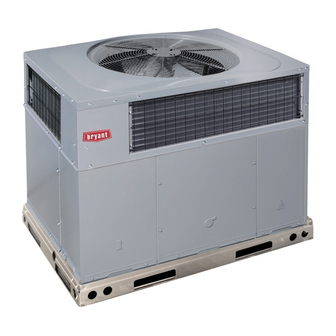
Fig. 1 - - Unit 574D- -- -A
(Low NOx Model Available)
. . . . . . . . . . . . . . . . . . . . . . . . .
. . . . . . . . . . . . . .
. . . . . . . . . . . . . . . . . . . . . . . . . . . .
. . . . . . . . . . . . . . . . . . . . . . . . . . . . . . . . . . .
. . . . . . . . . . . . . . . . . . . . . . . . . . . . . . . . .
. . . . . . . . . . . . . . . . . . . . . . . . . . . . . . . . . . .
. . . . . . . . . . . . . . . . . . . . . . . . . . . .
. . . . . . . . . . . . . . . . . . . . . . . . . . . . . . . . . . .
. . . . . . . . . . . . . . . . . . . . .
. . . . . . . . . . . . . . . . . . . . . . . . . . . . . . .
. . . . . . . . . . . . . . . . . . . . . . . . . . . . . .
. . . . . . . . . . . . . . . . . . . . . . . . . . . . . . . . . . . .
. . . . . . . . . . . . . . . . . . . . . . . . . . . . . .
. . . . . . . . . . . . . . . . . . . . . . . . . . . .
. . . . . . . . . . . . . . . . . . . . . . .
. . . . . . . . . . . . . . . . . . . . . . . . . . . . . . .
. . . . . . . . . . . . . . . . . . . . . . . . . . . . . . .
. . . . . . . . . . . . . . . . . . . . . . . . . . . . . .
. . . . . . . . . . . . . . . . . . . . . . . . . . . . . .
A09034
31
32
32
32
32
32
32
. . . .
32
33
34
34
34
34
34
35
35
40- -57
40
40
40
40- -41
44- -46
47- -55
56
57
Advertisement
Table of Contents
Troubleshooting

Related Manuals for Bryant Legacy 574D----A


Summary of Contents for Bryant Legacy 574D----A
-
Page 1: Table Of Contents
574D- -- -A LEGACYt 13 SEER SINGLE- -PACKAGED AIR CONDITIONER AND GAS FURNACE SYSTEM WITH PURONR (R- -410A) REFRIGERANT SINGLE AND THREE PHASE 2- -5 NOMINAL TONS (SIZES 24- -60) Installation Instructions NOTE: Read the entire instruction manual before starting the installation. -
Page 2: Introduction
(NFGC) NFPA 54/ANSI Z223.1, and the National Electrical Code These models meet the California maximum oxides of nitrogen (NEC) NFPA 70. (NOx) emissions requirements of 40 nanograms/joule or less as shipped from the factory and must be installed in California Air In Canada refer to the current editions of the National Standards of Quality Management Districts or any other regions in North Canada CAN/CSA- -B149.1 and .2 Natural Gas and Propane... - Page 3 A09469 Fig. 2 - - 574D- -- -A24- -36 Unit Dimensions...
- Page 4 A09470 Fig. 3 - - 574D- -- -A42- -60 Unit Dimensions...
- Page 5 Dashed lines show cross support location for large basepan units. HVAC unit HVAC unit basepan base rails Sealing Gasket Roofcurb Anchor screw Wood nailer* Flashing field supplied Roofcurb* Insulation (field supplied) Roofing material field supplied Cant strip field supplied A09413 SMALL/COMMON CURB *Provided with roofcurb A09090...
-
Page 6: Slab Mount
Only trained, qualified crane operators and ground support staff should handle and install this equipment. OPTIONAL OPTIONAL When working with this equipment, observe precautions in the RETURN SUPPLY literature, on tags, stickers, and labels attached to the equipment, OPENING OPENING and any other safety precautions that might apply. - Page 7 CAUTION - NOTICE TO RIGGERS PRUDENCE - AVIS AUX MANIPULATEUR ACCESS PANELS MUST BE IN PLACE WHEN RIGGING. PANNEAUX D'ACCES DOIT ÊTRE EN PLACE POUR MANIPULATION. Use top skid as spreader bar. / Utiliser la palette du haut comme barre de répartition DUCTS MINIMUM HEIGHT: 36"...
- Page 8 Table 1 – Physical Data - - Unit 574D- -- -A UNIT SIZE 24040 24060 30040 30060 36060 36090 42060 42090 NOMINAL CAPACITY (ton) 2 ---1/2 2 ---1/2 3 ---1/2 3 ---1/2 SHIPPING WEIGHT** lb. SHIPPING WEIGHT** (kg) Scroll COMPRESSORS Quantity REFRIGERANT (R --- 410A) Quantity lb.
-
Page 9: Connect Condensate Drain
Step 6 — Connect Condensate Drain 3. Secure flue hood to flue panel by inserting a single screw on the top flange and the bottom flange of the hood. NOTE: When installing condensate drain connection be sure to Step 8 — Install Gas Piping comply with local codes and restrictions. -
Page 10: Install Duct Connections
Table 2 – Maximum Gas Flow Capacity* LENGTH OF PIPE FT (m)† NOMINAL INTERNAL IRON PIPE DIAMETER SIZE (IN.) (IN.) (12) (15) (18) (21) (24) (27) (30) (38) (46) (53) (61) .622 — — .824 1.049 1--- 1/4 1.380 1400 1--- 1/2 1.610 2100... -
Page 11: Install Electrical Connections
Step 10 — Install Electrical Connections WARNING ELECTRICAL SHOCK HAZARD Failure to follow this warning could result in personal injury or death. The unit cabinet must have an uninterrupted, unbroken electrical ground. This ground may consist of an electrical wire connected to the unit ground screw in the control compartment, or conduit approved for electrical ground when installed in accordance with NFPA 70 (NEC) (latest edition) (in Canada, Canadian Electrical Code CSA C22.1) -
Page 12: Special Procedures For 208- -V Operation
2. Connect ground lead to chassis ground connection. 3. Locate the black and yellow wires connected to the line side HIGH VOLTAGE of the contactor (if equipped). POWER LEADS POWER (SEE UNIT WIRING 4. Connect field L1 to black wire on connection 11 of the SUPPLY LABEL) compressor contactor. -
Page 13: Pre- -Start- -Up
PRE- -START- - UP WARNING WARNING FIRE, EXPLOSION HAZARD Failure to follow this warning could result in personal ENVIRONMENTAL, FIRE, EXPLOSION, injury, death or property damage. ELECTRICAL SHOCK HAZARD Do not purge gas supply into the combustion chamber. Do Failure to follow this warning could result in personal not use a match or other open flame to check for gas leaks. -
Page 14: Check Heating Control
NOTE: Make sure that gas supply has been purged, and that all on natural gas with a heating value of 1025 Btu/ft at 0.60 gas piping has been checked for leaks. specific gravity, or propane gas with a heating value of 2500 Btu/ft at 1.5 specific gravity. -
Page 15: Check Burner Flame
3. 112.5 x 1 =112.5 ft of gas flow/hr. REGULATOR COVER SCREW 4. 112.5 x 1050 = 118,125 Btuh input. PLASTIC If the desired gas input is 115,000 Btuh, only a minor change in the ADJUSTMENT SCREW manifold pressure is required. ON/OFF SWITCH Observe manifold pressure and proceed as follows to adjust gas REGULATOR SPRING... - Page 16 A09282 Fig. 14 - - 208/230- -1- -60 Connection Wiring Diagram...
- Page 17 A09282 Fig. 14 Cont. - - 208/230- -1- -60 Ladder Wiring Diagram...
- Page 18 A09264 Fig. 15 - - 208/230- -3- -60 Connection Wiring Diagram...
- Page 19 A09264 Fig. 15 Cont. - - 208/230- -3- -60 Ladder Wiring Diagram...
- Page 20 A09265 Fig. 16 - - 460- -3- -60 Connection Wiring Diagram...
- Page 21 A09265 Fig. 16 Cont. - - 460- -3- -60 Ladder Wiring Diagram...
-
Page 22: Normal Operation
Normal Operation burners. When the temperature at the rollout switch reaches the maximum allowable temperature, the control circuit trips, closing An LED (light- -emitting diode) indicator is provided on the the gas valve and stopping gas flow to the burners. The indoor integrated gas unit controller (IGC) to monitor operation. -
Page 23: Indoor Airflow And Airflow Adjustments
Proceed as follows: 1. Remove the vinyl cap off of the desired speed tap wire (Refer to Table 6 for color coding). Table 9 shows the 1. Remove caps from low- - and high- -pressure service fittings. temperature rise associated with each fan speed for a given 2. -
Page 24: Cooling Sequence Of Operation
speed when the DH control lead is not energized, or IFB “HIGH” Table 6 – Color Coding for Indoor Fan Motor Leads speed when the DH lead is energized (see Fig. 17). Black = High Speed Orange = Med--- High Speed Red = Med Speed HEAT HIGH... - Page 25 Table 7 – Cooling Charging Chart A08490...
- Page 26 Table 8 – Filter Pressure Drop Table (IN. W.C.) FILTER SIZE in. (mm) 900 1000 1100 1200 1300 1400 1500 1600 1700 1800 1900 2000 2100 2200 2300 20X20X1 0.05 0.07 0.08 0.10 0.12 0.13 0.14 0.15 — — — —...
- Page 27 Table 9 - - Dry Coil Air Delivery* - - Horizontal and Downflow Discharge - - Unit 574D- -- -A24- -60 HEATING EXTERNAL STATIC PRESSURE (IN. W.C.) RISE MOTOR WIRE UNIT RANGE SPEED COLOR --- --- --- --- --- --- --- --- --- --- Heating...
- Page 28 Table 9 - - Dry Coil Air Delivery* - - Horizontal and Downflow Discharge - - Unit 574D- -- -A24- -60 HEATING EXTERNAL STATIC PRESSURE (IN. W.C.) RISE MOTOR WIRE UNIT RANGE SPEED COLOR 1234 1168 1093 1021 Heating Rise ( Blue Heating Rise (...
- Page 29 Table 9 - - Dry Coil Air Delivery* - - Horizontal and Downflow Discharge - - Unit 574D- -- -A24- -60 HEATING EXTERNAL STATIC PRESSURE (IN. W.C.) RISE MOTOR WIRE UNIT RANGE SPEED COLOR 1402 1351 1311 1263 1224 1172 1136 1080 1041...
- Page 30 Table 9 - - Dry Coil Air Delivery* - - Horizontal and Downflow Discharge - - Unit 574D- -- -A24- -60 HEATING EXTERNAL STATIC PRESSURE (IN. W.C.) RISE MOTOR WIRE UNIT RANGE SPEED COLOR 1445 1389 1341 1281 1236 1189 1139 1072 1027...
-
Page 31: Maintenance
Table 10 – 574D- -- -A Wet Coil Pressure Drop (IN. W.C.) STANDARD CFM (S.C.F.M) UNIT SIZE 1000 1100 1200 1300 1400 1500 1600 1700 1800 1900 2000 0.030 0.037 0.044 0.053 0.063 0.037 0.044 0.053 0.063 0.072 0.081 0.105 0.055 0.060 0.090... -
Page 32: Induced Draft (Combustion Air) Blower
1. Remove the induced draft blower assembly according to WARNING directions in the Induced Draft Blower Assembly section. 2. Remove the 11 screws holding the flue collector box cover ELECTRICAL SHOCK HAZARD (See 19) to the heat exchanger assembly. Inspect the heat exchangers. -
Page 33: Outdoor Fan
Integrated Gas Unit Controller BLOWER (IGC) HOUSING Auto Transformer fuses used on 460 volt units only. (Hidden) Interface Fan Board (IFB) Induced Draft Motor 2 SETSCREWS Fan Partition Flue (HIDDEN) Rollout Mounting Collector Inducer Switch Burner Bracket Mounting Blower Rack Screw Housing A09193... -
Page 34: Electrical Controls And Wiring
FAN GRILLE MOTOR MOTOR SHAFT A08505 MAX DISTANCE BETWEEN TOP OF FAN GRILLE AND BOTTOM OF FAN BLADE “A” SIZE Fig. 22 - - Fan Blade Position Electrical Controls and Wiring Gas Input Inspect and check the electrical controls and wiring annually. Be The gas input does not require checking unless improper heating sure to turn off the electrical power to the unit. -
Page 35: Troubleshooting
charge so that pressure gauges read 0 psig. Never open system designed for HCFC and CFC refrigerants. Take all necessary precautions to avoid exposure of the oil to the atmosphere. without breaking vacuum with dry nitrogen. Servicing Systems on Roofs with Synthetic Materials High- - Pressure Switch POE (polyolester) compressor lubricants are known to cause long The high- -pressure switch is located in the discharge line and... - Page 36 PURONR (R- -410A) QUICK REFERENCE GUIDE S Puron refrigerant operates at 50- -70 percent higher pressures than R- -22. Be sure that servicing equipment and replacement components are designed to operate with Puron S Puron refrigerant cylinders are rose colored. S Recovery cylinder service pressure rating must be 400 psig, DOT 4BA400 or DOT BW400.
- Page 37 Table 12 – Troubleshooting Chart SYMPTOM CAUSE REMEDY Power failure Call power company Fuse blown or circuit breaker tripped Replace fuse or reset circuit breaker Defective contactor, transformer, or high--pressure, Replace component loss--of--charge or low--pressure switch Compressor and condenser fan will not start. Insufficient line voltage Determine cause and correct Incorrect or faulty wiring...
- Page 38 Table 13 – Troubleshooting Guide–Heating SYMPTOM CAUSE REMEDY Water in gas line Drain. Install drip leg. No power to furnace Check power supply fuses, wiring or circuit breaker. Check transformer. No 24--v power supply to control circuit NOTE: Some transformers have internal over--current protection that requires a cool--down period to reset.
- Page 39 START- -UP CHECKLIST (Remove and Store in Job Files) I. PRELIMINARY INFORMATION MODEL NO.: SERIAL NO.: DATE: TECHNICIAN: II. PRESTART- -UP (Insert check mark in box as each item is completed) ( ) VERIFY THAT ALL PACKING MATERIALS HAVE BEEN REMOVED FROM UNIT ( ) REMOVE ALL SHIPPING HOLD DOWN BOLTS AND BRACKETS PER INSTALLATION INSTRUCTIONS ( ) CHECK ALL ELECTRICAL CONNECTIONS AND TERMINALS FOR TIGHTNESS ( ) CHECK GAS PIPING FOR LEAKS (WHERE APPLICABLE)
-
Page 40: Vertical Economizer
VERTICAL ECONOMIZER ACCESSORIES (FACTORY INSTALLED OPTION) The economizer has several field- -installed accessories available to optimize performance. Refer to Table 17 for authorized parts. GENERAL Economizers are recommended for only commercial packaged Table 17 – Accessory List products that have X13 motors. The Economizer system utilizes DESCRIPTION PART NUMBER the latest technology available for integrating the use of free... - Page 41 6. Replace horizontal return duct cover panel. Screw in place ensuring all seams are air and watertight. 7. Install the 2 angle filter brackets to the right and left hood side panels respectively with the #10 screws provided. See Fig. 26. 8.
- Page 42 Hood Divider (Removed) Hood Divider Horizontal Return Duct Cover Panel A09691 Fig. 25 - - Horizontal Return Duct Cover Panel Removal Right Hood Left Hood Side Panel Side Panel Filter Angle Bracket Filter Angle Bracket A09692 Fig. 26 - - Filter Angle Bracket Installation...
- Page 43 Hood Top Panel Right Hood Side Panel Hood Divider Left Hood Side Panel A09693 Fig. 27 - - Economizer Hood Assembly Filter Clips Aluminum Filter A09694 Fig. 28 - - Economizer Hood Installation A09695 Fig. 29 - - Filter Installation (See Through View)
-
Page 44: Large Chassis
Large Chassis 7. Install the 2 angle filter brackets to the right and left hood side panels respectively with the #10 screws provided. See To install the Vertical Economizer on the large chassis perform the Fig. 33. following procedure: 8. Assemble hood according to Fig. 34 screwing together with 1. - Page 45 A09698 Fig. 32 - - OAT Bracket Installation Left Hood Side Panel Filter Angle Bracket Right Hood Side Panel Filter Angle Bracket Left Hood Side Right Hood Side A09699 Fig. 33 - - Filter Angle Bracket Installation...
- Page 46 Right Hood Side Panel Hood Top Panel Left Hood Side Panel Hood Divider A09700 Fig. 34 - - Hood Assembly NOTE: The economizer control settings and the filters are accessible through the filter access door. Table 19 – Filter Part Number PART DESCRIPTION NUMBER...
-
Page 47: Configuration
CONFIGURATION Economizer Standard Sensors OUTDOOR AIR TEMPERATURE (OAT) SENSOR— The outdoor air temperature sensor (HH57AC080) is a 10 to 20mA device used to measure the outdoor- -air temperature. The outdoor- -air temperature is used to determine when the Economizer can be used for free cooling. - Page 48 Economizer Control Modes — Determine the Economizer control OUTDOOR ENTHALPY CHANGEOVER—For enthalpy mode before set up of the control. Some modes of operation may control, accessory enthalpy sensor (part number HH57AC078) is require different sensors. Refer to Table 16. The Economizer is required.
- Page 49 IAQ sensor should be wired to the AQ and AQ1 terminals of the 6000 controller. Adjust the DCV potentiometers to correspond to the DCV voltage output of the indoor air quality sensor at the user determined 5000 set point. See Fig. 43. If a separate field- -supplied transformer is used to power the IAQ sensor, the sensor must not be grounded or the 4000 800 ppm...
- Page 50 A10098 Fig. 45 - - Economizer Wiring Diagram...
- Page 51 A10075 Fig. 46 - - Connection Wiring Diagram 230- -3...
- Page 52 A10075 Fig. 46 Cont. - - Ladder Wiring Diagram 230- -3...
- Page 53 A10087 Fig. 47 - - Connection Wiring Diagram 460- -3...
- Page 54 A10087 Fig. 48 - - Ladder Wiring Diagram 460- -3...
- Page 55 DAMPER MOVEMENT — Damper movement from full open to The DCV set point may be left at 2 volts since the CO sensor voltage will be ignored by the Economizer controller until it rises full closed (or vice versa) takes 2 1/2 minutes. above the 3.6 volt setting of the minimum position potentiometer.
-
Page 56: Operation
Table 21 – CO Sensor Standard Settings VENTILATION OPTIONAL RELAY RATE CONTROL RELAY ANALOG SETTING EQUIPMENT OUTPUT HYSTERESIS (CFM/ OUTPUT RANGE SETPOINT (PPM) PERSON) (PPM) (PPM) 0--- 10V Proportional 0--- 2000 1000 4--- 20mA Interface w/Standard Building 2--- 10V Proportional 0--- 2000 1000 Control System... -
Page 57: Troubleshooting
TROUBLESHOOTING 5. Turn the DCV set point potentiometer CW until the DCV LED turns off. The DCV LED should turn off when the See Table 22 for Economizer logic. An Economizer simulator potentiometer is approximately 9- -v. The actuator should program is available to help with Economizer training and drive fully closed. - Page 58 A10064 Fig. 49 - - 574D- -- -A 30- -36 3 Phase with Economizer...
- Page 59 A10065 Fig. 50 - - 574D- -- -A 42- -60 3 Phase with Economizer...
- Page 60 Catalog No. II574D---08 E2010 Bryant Heating & Cooling Systems D 7310 W. Morris St. D Indianapolis, IN 46231 Printed in U.S.A. Edition Date: 04/10 Manufacturer reserves the right to discontinue, or change at any time, specifications or designs without notice and without incurring obligations.
Need help?
Do you have a question about the Legacy 574D----A and is the answer not in the manual?
Questions and answers
Can you tell me what size units this is? Is 18” flex duct appropriate size for the return air if filter is about 20 feet away?
The Bryant Legacy 574D----A is available in sizes ranging from 2 to 5 nominal tons (sizes 24–60).
An 18” flex duct for return air may not be appropriate if the filter is about 20 feet away, as longer duct runs can increase pressure drop and reduce airflow. The required airflow and static pressure loss should be checked to ensure proper system performance.
This answer is automatically generated