Table of Contents
Advertisement
Quick Links
Advertisement
Table of Contents
Troubleshooting

Related Manuals for Toshiba RAV-HM1401UTP Series


Summarization of Contents
Safety Caution
Definition of Qualified Installer or Qualified Service Person
Defines requirements for installers and service personnel for air conditioner installation and maintenance.
Protective Gear and Symbols
Explanation of Indications
Explains the meaning of danger, warning, and caution symbols.
Meaning of Symbols Displayed on the Unit
Explains symbols found on the unit, such as warning (risk of fire) and manual references.
Air Conditioner Warning Indications
Confirmation of Warning Label on Main Unit
Instructs to confirm warning labels on the main unit and re-stick them if removed.
Safety Precautions
DANGER
Details critical safety precautions related to electrical shock, handling parts, and general safety.
General Safety Precautions
General
General warnings for handling the air conditioner, including refrigerant safety and protective gear.
Prohibitions and Specific Handling
Prohibition of Modification
Warns against modifying parts, which could cause fire or electric shock.
Use Specified Parts
Emphasizes using only specified parts for replacement to avoid hazards.
Refrigerant Handling
Information about R32 refrigerant, its properties, and handling precautions.
Service Procedures and Checks
Assembly / Wiring
Guidelines for correct assembly and wiring to prevent disasters.
Check after Repair
Checks to perform after repair work, including leak checks and trial runs.
Operational Precautions
Installation
Guidelines for safe and proper installation, including refrigerant concentration and circuit breakers.
Relocation
Procedures and warnings for relocating the air conditioner by qualified personnel.
Declaration of Conformity
Manufacturer Information
Details about the manufacturer and TCF holder for compliance.
Declaration of Conformity (UK)
Manufacturer Information (UK)
Details about the manufacturer and TCF holder for UK compliance.
Specifications
Sound Pressure and Weight Data
Table listing sound pressure levels and weights for different models.
Detailed Specifications
Cooling and Heating Capacity
Specifies cooling and heating capacities for various models.
Power Supply and Electrical Characteristics
Details power supply requirements and electrical characteristics.
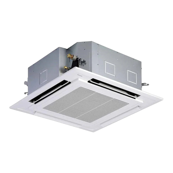
Indoor Unit Dimensions and Appearance
Provides dimensions and appearance details for indoor units and ceiling panels.
Refrigerant R32 Handling
Safety Caution Concerned to Refrigerant R32
Highlights safety concerns related to R32 refrigerant pressure and oil changes.
Cautions on Installation/Service
Provides cautions for installation and service regarding refrigerant mixing and pipe materials.
Pipe Materials
Specifies requirements for copper pipes and joints used with R32 refrigerant.
Tools for R32 Refrigerant Systems
Required Tools for R32
Lists tools exclusive and common for R32 installation and service.
Construction Views (External)
Indoor Unit Dimensions and Mounting
Shows external dimensions and mounting details for the indoor unit and ceiling panel.
Refrigerating Cycle Diagrams
Single Type System Diagram
Illustrates the refrigerating cycle for a single indoor and outdoor unit combination.
Refrigerating Cycle Diagrams (Continued)
Triple Type System Diagram
Illustrates the refrigerating cycle for a triple indoor unit and one outdoor unit system.
Refrigerating Cycle Diagrams (Continued)
Double-twin Type System Diagram
Illustrates the refrigerating cycle for a double-twin (4 indoor units) system.
Wiring Diagram
Indoor Unit Wiring Diagram
Shows the wiring connections for the 4-way cassette type indoor unit.
Electrical Parts Specifications
RAV-HM561UTP*, RAV-HM801UTP* Specifications
Lists electrical parts and their specifications for specific models.
Indoor Control Circuit
Indoor Controller Block Diagram
Shows the block diagram of the indoor unit controller.
Connection of Wired (Simple) Remote Controller
Illustrates how to connect a wired remote controller to the indoor unit.
Indoor Control Circuit (Continued)
Connection of Wireless Remote Controller Kit
Shows how to connect a wireless remote controller kit.
Control Specifications
Operation Mode Selection
Explains how to select operation modes via the remote controller.
Room Temperature Control
Details the adjustment range for room temperature settings.
Control Specifications (Continued)
Automatic Capacity Control (GA Control)
Explains automatic capacity control based on temperature differences.
Automatic Cooling/Heating Control
Describes automatic switching between cooling and heating modes.
Control Specifications (Continued)
Air Speed Selection
Details how air speed is selected based on temperature and operation mode.
Control Specifications (Continued)
Air Speed Selection (Continued)
Provides details on air speed selection based on dip switch settings and revolution speeds.
Control Specifications (Continued)
Cool Air Discharge Preventive Control
Explains control to prevent cold air discharge during heating operation.
Freeze Preventive Control (Low Temperature Release)
Details freeze prevention control based on temperature sensors.
Control Specifications (Continued)
High-temp. Release Control
Explains control for high-temperature release based on sensor readings.
Drain Pump Control
Describes the operation and check codes for the drain pump.
Control Specifications (Continued)
Louver Control
Details how to set louver positions and air direction.
Control Specifications (Continued)
Louver Control (Continued)
Explains swing modes and louver lock functions.
Control Specifications (Continued)
HA Control
Explains HA control for remote start/stop and status output.
Frequency Fixed Operation (Test Run)
Procedure for performing a test run with fixed frequency.
Control Specifications (Continued)
Energy-saving Control
Explains energy-saving operation and temperature adjustments.
Max. Frequency Cut Control
Details maximum frequency cut control for cooling and heating.
Control Specifications (Continued)
Self-clean Operation (Dry Operation)
Explains self-clean operations performed after cooling or dry mode stops.
Power Saving (Energy Saving Operation)
Details power saving settings and restriction ratios.
Control Specifications (Continued)
8°C Heating/Frost Protective Operation
Describes the 8°C heating and frost protective operation for cold latitudes.
Occupancy Sensor
Explains occupancy sensor operation and absence detection settings.
Control Specifications (Continued)
Soft Cooling
Describes soft cooling function for draft suppression.
Draft Prevention Control
Explains draft prevention control during defrost operations.
Control Specifications (Continued)
Communication Type Setting
Details setting communication types (TCC-Link, TU2C-Link).
Rotation / Backup Operation
Explains rotation control and backup operation for multiple units.
Control Specifications (Continued)
Rotation / Backup Operation (Continued)
More details on rotation intervals, lap times, and monitor functions.
Defrost Shift
Describes changing defrost operation start times to avoid temperature drops.
Control Specifications (Continued)
Power Shift
Explains power shift control for balancing load and reducing power consumption.
Control Specifications (Continued)
Free Cooling
Details free cooling operation based on outdoor temperature for energy saving.
Control Specifications (Continued)
Secondary Heating
Explains secondary heating function for cold latitudes and flip modes.
Control Specifications (Continued)
Secondary Heating (Continued)
Provides wiring and setup details for secondary heating.
Indoor Print Circuit Board
MCC-1643 Component Layout
Diagram showing the layout of components and connectors on the indoor P.C. board.
Indoor P.C. Board Specifications
Optional Connector Specifications
Details specifications for optional connectors like Ventilation, HA, and Occupancy sensor.
Troubleshooting
Before Troubleshooting
Lists required tools and confirmation points before troubleshooting.
Troubleshooting Procedure
Outlines the general procedure for troubleshooting issues.
Troubleshooting (Continued)
Before Troubleshooting (Wireless Remote Controller)
Confirmation points and tools needed before troubleshooting wireless models.
Troubleshooting Procedure (Wireless Remote Controller)
General troubleshooting steps for wireless remote controller issues.
Troubleshooting Details
Outline of Judgment
Method to judge troubleshooting positions using lamp indications and check codes.
Troubleshooting Details (Continued)
Check Code List (Indoor Unit Sensors)
Lists check codes related to indoor unit sensor troubles.
Troubleshooting Details (Continued)
Other (Other than Check Code)
Troubleshooting for issues not covered by specific check codes, like test runs.
Troubleshooting Details (Continued)
Check Code List (Indoor)
Comprehensive list of indoor unit check codes and their causes.
Troubleshooting Details (Continued)
Trouble Mode Detected by Indoor Unit
Details troubleshooting based on diagnostic function and causes.
Troubleshooting Details (Continued)
Trouble Mode Detected by Remote Controller or Central Controller
Troubleshooting for issues detected via remote or central controllers.
Troubleshooting Diagnostic Procedures
Diagnostic Procedure for E01 Trouble
Step-by-step diagnosis for E01 trouble related to remote controller communication.
Diagnostic Procedure for E09 Trouble
Step-by-step diagnosis for E09 trouble related to master/follower unit communication.
Troubleshooting Diagnostic Procedures (Continued)
Diagnostic Procedure for E04 Trouble
Troubleshooting steps for E04 trouble, checking outdoor operation and wiring.
Troubleshooting Diagnostic Procedures (Continued)
Diagnostic Procedure for E11 Trouble
Troubleshooting steps for E11 trouble related to the Application control kit.
Troubleshooting Diagnostic Procedures (Continued)
Diagnostic Procedure for E18 Trouble
Troubleshooting steps for E18 trouble related to inter-unit cable and group control.
Diagnostic Procedures for E08, L03, L07, L08 Troubles
Addresses issues of duplicated units, group addresses, and unset capacity.
Troubleshooting Diagnostic Procedures (Continued)
Diagnostic Procedure for L20 Trouble
Troubleshooting for issues with multiple central control system addresses.
Diagnostic Procedure for L30 Trouble
Troubleshooting for issues with outside devices and wiring.
Diagnostic Procedure for P30 Trouble (Central controller)
Troubleshooting for central controller related issues.
Troubleshooting Diagnostic Procedures (Continued)
Diagnostic Procedure for P10 Trouble
Troubleshooting steps for P10 trouble related to float switch and drain pump.
Diagnostic Procedure for F10 Trouble
Troubleshooting steps for F10 trouble related to TA sensor.
Troubleshooting Diagnostic Procedures (Continued)
Diagnostic Procedure for P12 Trouble
Troubleshooting steps for P12 trouble related to the fan motor and PC board.
Troubleshooting Diagnostic Procedures (Continued)
Diagnostic Procedure for P19 Trouble
Troubleshooting for P19 trouble related to the 4-way valve.
Diagnostic Procedure for F02 Trouble
Troubleshooting steps for F02 trouble related to the TC sensor.
Diagnostic Procedure for F01 Trouble
Troubleshooting steps for F01 trouble related to the TCJ sensor.
Troubleshooting Diagnostic Procedures (Continued)
Diagnostic Procedure for F30 Trouble
Troubleshooting steps for F30 trouble related to the occupancy sensor.
Troubleshooting Diagnostic Procedures (Continued)
Diagnostic Procedure for C06 Trouble ('1:1 model' connection interface)
Troubleshooting for C06 trouble with the 1:1 model connection interface.
Troubleshooting Details (Continued)
E03 Trouble (Header Indoor Unit)
Explains E03 trouble related to remote controller signal reception.
F29 Trouble
Details F29 trouble related to EEPROM on the indoor unit P.C. board.
P31 Trouble (Follower Indoor Unit)
Explains P31 trouble detected by follower units when header has issues.
Temperature Sensor Characteristics
TA, TC, TCJ Sensor Resistance Values
Provides resistance value characteristics for TA, TC, and TCJ sensors versus temperature.
Service P.C. Board Replacement
CAUTION
General caution regarding P.C. board replacement settings.
Replacement Procedures - CASE 1
Procedure for replacing P.C. board when setting data can be read from EEPROM.
Replacement Procedures - CASE 2
Procedure for replacing P.C. board when setting data cannot be read from EEPROM.
Service P.C. Board Replacement (Continued)
Setting Data Read Out from EEPROM
Steps to read EEPROM data using RBC-ASCU1* remote controller.
Setting Data Read Out from EEPROM
Steps to read EEPROM data using RBC-AMTU3* remote controller.
Service P.C. Board Replacement (Continued)
CODE No. Required at Least
Lists essential CODE Nos. required for setting data after P.C. board replacement.
Service P.C. Board Replacement (Continued)
Step 2: System Configuration
Guides on turning on the unit after P.C. board replacement based on system type.
Service P.C. Board Replacement (Continued)
[3] Writing the Setting Data to EEPROM
Detailed steps for writing setting data to EEPROM using RBC-ASCU1*.
Service P.C. Board Replacement (Continued)
[3] Writing the Setting Data to EEPROM
Detailed steps for writing setting data to EEPROM using RBC-AMTU3*.
Service P.C. Board Replacement (Continued)
Table 1: Type: CODE No. 10
Lists type settings for CODE No. 10.
Setup at Local Site and Others
Indoor Unit - Test Run Setup on Remote Controller
Procedure for performing a test run setup on the remote controller.
Setup at Local Site and Others (Continued)
Test Run Setup on Remote Controller
Test run setup procedure for RBC-AMTU3* remote controller.
Test Run Setup
Test run setup procedure for wireless remote controllers.
Setup at Local Site and Others (Continued)
Forced Defrost Setup of Remote Controller (For wired remote controller only)
Procedure for forced defrost setup using wired remote controllers.
LED Display on P.C. Board
Explains the meaning of LED indicators on the P.C. board.
Setup at Local Site and Others (Continued)
Function Selection Setup
Procedure for function selection setup using RBC-ASCU1* remote controller.
Setup at Local Site and Others (Continued)
Function Selection Setup
Procedure for function selection setup using RBC-AMTU3* remote controller.
Function Code Table
DN Code Table (Part 1)
Lists function codes (DN) and their descriptions for various settings.
Function Code Table (Continued)
DN Code Table (Part 2)
Continues the list of function codes (DN) and their descriptions.
Function Code Table (Continued)
DN Code Table (Part 3)
Further lists function codes (DN) and their descriptions, including communication types.
Remote Controller Wiring and Setting
2-Remote Controller Control
Explains control with two remote controllers for twin or single indoor units.
How to Set Remote Controller as Follower Remote Controller
Guides on setting remote controllers as followers using DIP switches.
Remote Controller Wiring and Setting (Continued)
Wireless Remote Controller A-B Selection
Details the A-B selection process for wireless remote controllers.
Remote Controller Monitor Function
Calling of Sensor Temperature Display
Procedure to call sensor temperature display using RBC-ASCU1*.
Calling of Sensor Temperature Display
Procedure to call sensor temperature display using RBC-AMTU3*.
Remote Controller Monitor Function (Continued)
Indoor Unit Data
Lists data items available for monitoring from indoor units.
Remote Controller Monitor Function (Continued)
Calling of Trouble History
Procedure to view troubleshooting history using RBC-ASCU1*.
Remote Controller Monitor Function (Continued)
Trouble History
Procedure to view troubleshooting history using RBC-AMTU3*.
Indoor Unit Power-ON Sequence
Indoor Unit Power-ON Sequence
Diagram illustrating the power-ON sequence and address setup.
Setup at Local Site / Others (Continued)
1:1 Model Connection Interface Function
Explains the function of the 1:1 model connection interface.
1:1 Model Connection Interface Wiring Connection
Details wiring connections for the 1:1 model interface.
Setup at Local Site / Others (Continued)
Wiring Specifications
Specifies wiring requirements for central control systems.
P.C. Board Switch (SW01) Setup
Instructions for setting up the P.C. board switch (SW01).
Setup at Local Site / Others (Continued)
How to Set up Central Control Address Number
Procedure to set central control address number using remote controller.
Address Setup
Address Setup Procedure
Outlines the procedure for setting up addresses for indoor units.
Address Setup & Group Control
System Configuration
Illustrates system configurations for single, twin, and group operations.
Address Setup & Group Control (Continued)
Multiple Groups Operation (Manual Address Setting)
Details manual address setting for multiple groups.
Address Setup & Group Control (Continued)
Automatic Address Example from Unset Address
Examples of automatic address setup for standard, group, and multiple group operations.
Manual Address Setup via Remote Controller
Address Setup Procedure
Step-by-step guide for manual address setup using RBC-ASCU1*.
Manual Address Setup via Remote Controller (Continued)
Indoor Unit Address
Steps to set indoor unit addresses.
Maintenance and Check List
Maintenance Checklist
Table detailing checks and maintenance for heat exchanger, fan motor, filter, etc.
Detachments and Attachments
Suction Grille
Instructions for detaching and attaching the suction grille for RBC-U32P**.
Detachments and Attachments (Continued)
Electric Parts Cover
Procedure for detaching and attaching the electric parts cover.
Detachments and Attachments (Continued)
Adjust Corner Cap
Instructions for detaching and attaching the adjust corner cap for RBC-U32P**.
Detachments and Attachments (Continued)
Adjust Corner Cap
Instructions for detaching and attaching the adjust corner cap for RBC-U33P**.
Detachments and Attachments (Continued)
Ceiling Panel
Procedure for detaching and attaching the ceiling panel for RBC-U32P**.
Detachments and Attachments (Continued)
Ceiling Panel
Procedure for detaching and attaching the ceiling panel for RBC-U33P**.
Detachments and Attachments (Continued)
Control P.C. Board
Procedure for detaching and attaching the control P.C. board.
Detachments and Attachments (Continued)
Drain Cap
Procedure for detaching and attaching the drain cap.
Detachments and Attachments (Continued)
Fan Motor
Procedure for detaching and attaching the fan motor.
Detachments and Attachments (Continued)
Fan Motor (Continued)
Continues the procedure for detaching and attaching the fan motor.
Detachments and Attachments (Continued)
Drain Pump
Procedure for detaching and attaching the drain pump.
Detachments and Attachments (Continued)
Float Switch Assembly
Procedure for detaching and attaching the float switch assembly.
Drain Pan
Procedure for detaching and attaching the drain pan.
Detachments and Attachments (Continued)
Heat Exchanger
Procedure for detaching and attaching the heat exchanger.
Exploded Views and Parts List
Indoor Unit Exploded View (Models 561/801)
Exploded view of the indoor unit for models 561UTP and 801UTP.
Exploded Views and Parts List (Continued)
Parts List (Models 561/801)
List of parts for indoor unit models 561UTP and 801UTP with location numbers.
Exploded Views and Parts List (Continued)
Indoor Unit Exploded View (Models 901/1101/1401/1601)
Exploded view of the indoor unit for models 901UTP and higher.
Exploded Views and Parts List (Continued)
Parts List (Models 901/1101/1401/1601)
List of parts for indoor unit models 901UTP and higher.
Exploded Views and Parts List (Continued)
Electric Parts List
List of electric parts with their corresponding part numbers and models.
Exploded Views and Parts List (Continued)
RBC-U32PGP-E Parts List
List of parts for the RBC-U32PGP-E ceiling panel.
Exploded Views and Parts List (Continued)
RBC-U33P-E Parts List
List of parts for the RBC-U33P-E ceiling panel.
Warnings on Refrigerant Leakage
Check of Concentration Limit
Information on refrigerant concentration limits and required room volume for safety.
Need help?
Do you have a question about the RAV-HM1401UTP Series and is the answer not in the manual?
Questions and answers