Advertisement
Quick Links
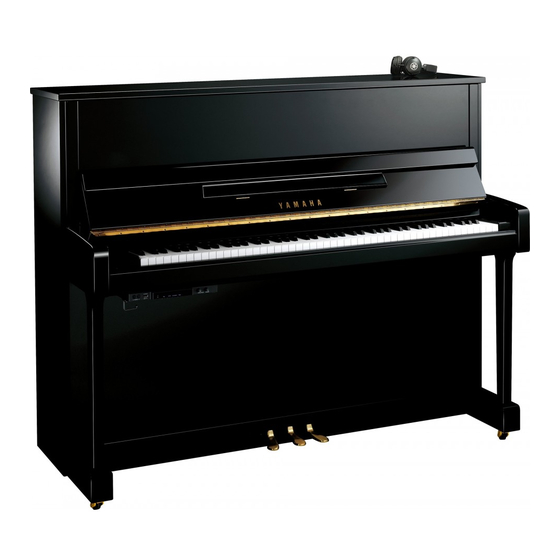
SILENT SD SERIES
¥560,000
YM5SD
(本体価格)
¥710,000
YU11SD
(本体価格)
YU11W-SD ¥850,000 2006年9月20日発売
(本体価格)
¥840,000
YU33SD
(本体価格)
YU33W-SD ¥980,000
(本体価格)
PP
008157
SERVICE MANUAL
YM5SD/YU11SD/YU11W-SD
YU33SD/YU33W-SD
YM5SD
CONTENTS
SPECIFICATIONS
SWITCH BOX & PEDAL
(スイッチボックスとペダル)
CIRCUIT BOARD LAYOUT
DISASSEMBLY PROCEDURE
LSI PIN DESCRIPTION
IC BLOCK DIAGRAM
CIRCUIT BOARDS
TEST MODE, ADJUSTMENT
YU33SD
(テストモード、調整)
CHECKING VERSIONS AND TYPES
(バージョン、プログラム種別の確認)
SWITCH BOX SELF-TEST MODE
(スイッチボックス自己診断機能)
PARTS LIST
BLOCK DIAGRAM, UNIT COMPARISON
(ブロックダイアグラム、ユニット表)
WIRING
(結線図)
OVERALL CIRCUIT DIAGRAM
Copyright (c) Yamaha Corporation. All rights reserved. PDF
(目次)
(総合仕様)
................................. 3
................................... 4
(ユニットレイアウト)
(分解手順)
(LSI端子機能表)
(ICブロック図)
(シート基板図)
......................... 16
....................................... 20/22
.......................... 28
(総回路図)
HAMAMATSU, JAPAN
YU11SD
... 5
............... 6
................ 13
.................... 15
............. 24/26
'06.09
Advertisement

Related Manuals for Yamaha SILENT Piano YM5SD


Summarization of Contents
Important Notices and Warnings
General Safety and Service Precautions
Guidance on safe and proper servicing procedures to prevent injury and product damage.
Chemical Content Warning
Notice regarding the presence of lead and other chemicals in product components.
UK Power Adapter Connection
Specific instructions for connecting the power adapter plug and cord in the UK.
Component Handling Warning
Warning about handling components with special characteristics and proper replacement.
Product Specifications
Technical Specifications Table
Detailed technical specifications including keyboard, pedal, voice, and sensor details.
Switch Box and Pedal Components
Switch Box Front Panel Controls
Description of controls and sockets located on the front panel of the switch box.
Switch Box Rear Panel Connectors
Identification of connectors on the rear panel of the switch box unit.
Circuit Board Layouts
YU11SD Circuit Board Arrangement
Diagrams illustrating the layout of circuit boards within the YU11SD piano model.
Disassembly Procedures
Switch Box Unit Removal
Step-by-step instructions for safely removing the switch box unit from the piano.
Switch Box Unit Disassembly Steps
Detailed steps for disassembling the switch box front panel, upper case, and circuit boards.
AM Circuit Board Removal
Procedure for removing the AM circuit board from the switch box unit.
Exterior and Keyboard Removal
YU11SD Front Board Removal
Instructions for removing the upper and lower front boards of the YU11SD piano model.
Key Stopper and Keyboard Removal
Procedure for removing the key stopper and all piano keyboards safely.
Electrical Components
Key Sensor Unit and Circuit Board
Details on removing the key sensor unit and its associated circuit board.
Pedal Unit L and S Removal
Instructions for removing the Pedal Unit L (Damper) and Pedal Unit S (Soft).
LSI Pin Descriptions
YMW767-VTZ CPU Pinout Example
Description of LSI pin functions for the YMW767-VTZ CPU, providing specific examples.
CPU and DAC LSI Pinouts
Detailed pin descriptions for various CPU and DAC LSIs used in the system.
IC Block Diagrams
Integrated Circuit Block Diagrams
Schematic block diagrams illustrating the internal logic of various integrated circuits.
Circuit Board Diagrams
AM Circuit Board Layout
Diagram showing the component layout on the AM circuit board.
DM Circuit Board Layout
Diagrams illustrating the component and pattern sides of the DM circuit board.
DC-IN and Key Sensor Circuit Boards
Diagrams for DC-IN and Key Sensor circuit boards (component and pattern sides).
Test Mode and Adjustment Procedures
Key Sensor Adjustment (All Keys)
Procedure for adjusting the key sensor by measuring and setting values for all keys.
One Key and Damper Pedal Adjustment
Steps for measuring and adjusting individual keys and the damper pedal sensor.
Sensor Test Mode
Procedure to enter and perform sensor tests on the key and pedal sensor units.
Switch Box Self-Test Mode
Self-Test Procedure and Tests
Steps to initiate the switch box self-test and descriptions of the communication and AD tests.
Parts List
Destination Abbreviations and Warnings
List of destination codes and crucial warnings regarding component replacement.
Unit Comparison Table
Table comparing component units across different SILENT SD Series models.
Parts List Details
Detailed listing of specific parts, including reference numbers, part numbers, and descriptions.
Accessories List
List of included accessories such as headphones and adapters.
Overall Assembly Diagram
YU11SD Component Layout
Diagram showing the overall assembly and placement of major components in the YU11SD model.
Key Sensor Unit Details
Key Sensor Unit Assembly Diagrams
Visual representations of the key sensor unit from top, rear, and bottom views.
Key Sensor Unit Parts List
List of individual parts that constitute the key sensor unit assembly.
Switch Box Unit Diagram
Switch Box Unit Exploded View
Diagram showing the exploded view of the switch box unit for assembly reference.
Switch Box Unit Parts List
List of all parts required for the assembly and disassembly of the switch box unit.
Pedal Unit L Details
Pedal Unit L Assembly Diagrams
Visual representations of the Pedal Unit L from left, top, and front views.
Pedal Unit L Parts List
List of individual parts that make up the Pedal Unit L assembly.
Pedal Unit S Details
Pedal Unit S Assembly Diagrams
Visual representations of the Pedal Unit S from left and top views.
Pedal Unit S Parts List
List of individual parts that make up the Pedal Unit S assembly.
Electrical Parts List
AM, DC-IN, and Key Sensor Board Components
List of electrical components used on the AM, DC-IN, and Key Sensor circuit boards.
Overall Circuit Diagram and Unit Comparison
DM Block Diagram and Unit Comparison
DM block diagram and unit comparison table for SILENT SD SERIES.
Wiring Diagram
Unit Connection Diagram and Table
Diagram illustrating the wiring connections between various units and components.
Detailed Circuit Diagrams
DM Section Block Diagram
Detailed block diagram of the DM section, showing component interconnections.
AM, DC-IN, Key Sensor Block Diagrams
Detailed block diagrams for AM, DC-IN, and Key Sensor sections, illustrating circuit logic.
Need help?
Do you have a question about the SILENT Piano YM5SD and is the answer not in the manual?
Questions and answers