
Related Manuals for BRUEL & KJAER PULSE 3560-C


Summarization of Contents
Chapter 1 Introduction
About this Manual
Explains the structure and content of the manual, covering installation, hardware, and appendices.
Glossary
Defines key terms and acronyms used throughout the PULSE system documentation.
Chapter 2 Installation and Configuration
Recommended PC Configuration
Details the hardware and software specifications required for the PC to install and run PULSE.
Connecting the PC to the Front-end
Describes network connection methods, including direct and dual network setups.
Preparing your PC for Installation of PULSE
Outlines the necessary steps to configure the PC before installing the PULSE software.
PULSE Software Installation
Provides instructions for installing the PULSE software, including administrator privileges.
License Fulfilment Procedure
Explains the process of fulfilling PULSE software licenses using mini-CD or online methods.
PULSE Hardware Setup
Guides through the process of setting up the PULSE front-end hardware and synchronization.
Setting Up the System
Details how to use the PULSE Front-end Setup program for configuration.
Set the PC IP Address
Instructions on how to configure the PC's IP address for network connectivity.
Define a New Configuration
Describes how to create a new front-end configuration within the setup program.
Single Frame Setup
Step-by-step guide for configuring a single PULSE front-end unit.
Multiple Frame Setup
Procedure for configuring a PULSE system with multiple front-end frames.
Front-end Browser
Explains how to use the Front-end Browser for managing front-ends on the LAN.
Chapter 3 Start-up and Testing
Digital Self-test
Describes the automatic self-test performed by modules upon power-up.
Analog Hardware Test
Details the process for running analog hardware self-tests on the system.
Network Troubleshooting
Provides steps for diagnosing and resolving network connectivity issues.
User Test Program – Verifying System Operation
Explains how to use the user test program to verify system functionality.
Chapter 4 Introduction to Hardware
What is an IDAe System?
Defines the IDAe system and its core components.
Overview of Hardware
Provides a comprehensive overview of the available hardware for PULSE systems.
Dyn-X Modules
Introduces Dyn-X modules and their advanced features.
Grounding Considerations
Discusses common grounding issues and methods to avoid them.
Chapter 5 Data Acquisition Units
Portable PULSE Type 3560-B
Describes the features and specifications of the portable 3560-B unit.
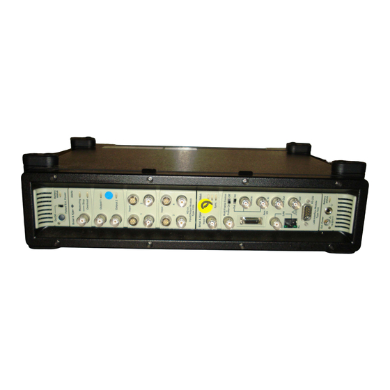
Portable PULSE Type 3560-C
Details the features and specifications of the portable 3560-C unit.
Multichannel Portable PULSE Type 3560-D
Describes the features and specifications of the multichannel 3560-D unit.
Multichannel PULSE Type 3560-E
Details the features and specifications of the multichannel 3560-E unit.
Chapter 6 Controller and Input/Output Modules
LAN Interface Module Type 7533
Details the LAN interface module, its connectors, LEDs, and protocols.
100 Mbit Controller Module Type 7536
Describes the 100 Mbit controller module, its features, and connectors.
5/1-ch. Input/Output Controller Modules Types 7537, 7537-A, 3560-B-010, 3560-B-020
Details 5/1-channel input/output controller modules and their common features.
5/1-ch. Dyn-X Input/Output Controller Modules Types 7538, 7538-A, 3560-B-110, 3560-B-120
Describes 5/1-channel Dyn-X I/O controller modules and common features.
5/1-ch. Input/Output Controller Modules with Generator Types 7539, 7539-A, 3560-B-030, 3560-B-040
Details 5/1-channel I/O controller modules with generators and common features.
6-ch. Dyn-X Charge & CCLD Input Module Type 3035
Describes the 6-channel Dyn-X module for charge and CCLD inputs.
12-ch. Input Modules Types 3038, 3038-B
Details the 12-channel input modules and their common features.
6-ch. Input Modules Types 3039, 3039-B
Describes the 6-channel input modules and their common features.
12-ch. Dyn-X Input Modules Types 3040, 3040-B
Details the 12-channel Dyn-X input modules and common features.
6-ch. Dyn-X Input Modules Types 3041, 3041-B
Describes the 6-channel Dyn-X input modules and their common features.
Generator, 4/2-ch. Input/Output Module Type 3109
Details the 4/2-channel generator input/output module.
Generator, 2/1-ch. Input/Output Module Type 3110
Describes the 2/1-channel generator input/output module.
Chapter 7 Connectors, Controls and Indicators
Aux. I/O
Details the Auxiliary Input/Output connector and its functions.
RS-232 (Serial Interface)
Describes the RS-232 serial interface connector and its uses.
BNT Connector
Explains the BNT connector and its signal input capabilities.
BNC/TNC Input Connector
Details the BNC/TNC input connector for signal input.
Overload
Explains the meaning of overload indications on input/output modules.
Chapter 8 Cables, Adaptors and Accessories
Signal Cables and Connectors
Lists and describes various signal cables and connectors for PULSE systems.
LAN Accessories
Details accessories for setting up wired and wireless LAN connections.
Power
Lists power-related accessories such as cables, batteries, and chargers.
Rack Mounting
Describes accessories for mounting PULSE systems in racks.
Other Accessories
Lists miscellaneous accessories for PULSE systems.
Chapter 9 Wireless LAN
Hardware
Details the hardware components for wireless LAN connectivity.
System and Antenna Configurations
Explains different ways to set up wireless LAN systems and antenna configurations.
Installing the System
Provides instructions for installing the wireless LAN system.
Chapter 10 Calibration
PULSE Services at Br¸el & KjÊr
Outlines calibration and maintenance services offered by Br¸el & KjÊr.
Available Calibration for PULSE Modules
Lists the types of calibration available for PULSE modules.
Chapter 11 Specifications
Compliance with Standards
Details the standards and certifications the equipment complies with.
Specifications – PULSE Types 3560-B/C/D/E
Provides general specifications for the PULSE system types.
Specifications – Input Channels, Standard 24-bit and Dyn-X
Contains detailed technical specifications for input channels.
Chapter 12 Service and Repair
Faults that Impair Safety of the System
Describes immediate actions for system faults that affect safety.
Faults that Impair Function but not Safety
Outlines procedures for faults that affect system function but not safety.
Appendix A Connecting Type 7533
Network Connection using 10 base 2
Explains how to set up a 10 base 2 network connection using BNC connectors.
Connection of Synchronization Cables
Details how to connect synchronization cables for multi-frame setups using IDA/BNT.
Appendix B Specifications of Discontinued Modules
10 Mbit LAN Interface Module Type 7533
Provides specifications for the discontinued 10 Mbit LAN Interface Module Type 7533.
Appendix C Discontinued Hardware
DSP-based Hardware
Lists DSP-based hardware that is no longer supported by PULSE.
IDA Modules
Lists IDA modules, including the discontinued 6-ch. A & V Recording Module Type 3030.
Need help?
Do you have a question about the PULSE 3560-C and is the answer not in the manual?
Questions and answers