Table of Contents
Advertisement
Quick Links
KA01129F/00/EN/04.22-00
71575729
2022-08-01
Products
Brief Operating Instructions
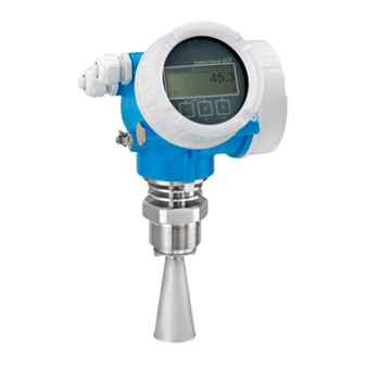
Micropilot FMR51, FMR52
PROFIBUS PA
Free space radar
These Instructions are Brief Operating Instructions; they are
not a substitute for the Operating Instructions pertaining to
the device.
Detailed information about the device can be found in the
Operating Instructions and the other documentation:
Available for all device versions via:
• Internet:
www.endress.com/deviceviewer
• Smart phone/tablet: Endress+Hauser Operations App
Solutions
Services
Advertisement
Table of Contents

Related Manuals for Endress+Hauser Micropilot FMR52 PROFIBUS PA


Summarization of Contents
Associated documentation
www.endress.com/deviceviewer
Online portal for accessing device information and documentation.
Endress+Hauser Operations App
Mobile application for accessing device information and documentation.
About this document
Safety symbols
Details hazard symbols like DANGER, WARNING, CAUTION.
Electrical symbols
Describes electrical symbols used in the document.
Tool symbols
Illustrates symbols for tools like screwdrivers and wrenches.
Basic safety instructions
Requirements for the personnel
Specifies qualifications and authorization for personnel performing tasks.
Intended use
Describes the device's purpose for continuous, non-contact level measurement.
Residual risks
Highlights risks like burns from hot surfaces during operation.
Workplace safety
Emphasizes wearing required personal protective equipment.
Operational safety
Ensures the device is in proper technical condition for safe operation.
Hazardous area
Guidelines for safe use in hazardous areas, including explosion protection.
Incoming acceptance and product identification
Incoming acceptance
Checks to perform during device receipt and inspection.
Storage conditions
Specifies permitted storage temperature and packaging requirements.
Transporting the product to the measuring point
Instructions for safely moving the device to its installation location.
Mounting
Mounting location
Guidance on selecting the optimal installation position for the device.
Internal vessel fittings
Consideration of internal components that may affect signal measurement.
Avoiding interference echoes
Methods to prevent unwanted signal reflections within the vessel.
Beam angle
Defines the beam angle and its relationship to beam diameter and distance.
Horn antenna (FMR51)
Alignment instructions for FMR51 horn antenna installation.
Nozzle height for horn antenna (FMR51)
Table specifying maximum nozzle heights for FMR51 horn antennas.
Nozzle diameter D
Table correlating nozzle diameter with maximum nozzle height and antenna.
Horn antenna, flush mount (FMR52)
Alignment instructions for FMR52 flush mount horn antenna installation.
Mounting cladded flanges
Notes for installing cladded flanges, including screw tightening.
Turning the transmitter housing
Instructions for rotating the transmitter housing for easier access.
Turning the display
Procedures for adjusting the orientation of the display module.
Electrical connection
Connecting requirements
Prerequisites and safety measures for electrical connections.
Terminal assignment
Details pin assignments for PROFIBUS PA/FOUNDATION Fieldbus.
Terminal assignment PROFIBUS PA / FOUNDATION Fieldbus
Diagrams showing terminal assignments for different configurations.
Block diagram PROFIBUS PA / FOUNDATION Fieldbus
Illustrates the functional connections of the device in the network.
Pin assignment of M12 plug
Pinout details for the M12 connector used for signals.
Supply voltage
Specifies voltage requirements and approvals for PROFIBUS PA/FOUNDATION Fieldbus.
Connecting the device
Steps and precautions for connecting the device, including explosion hazards.
Plug-in spring-force terminals
Explanation of connecting via spring-force terminals without levers.
Closing the cover of the connection compartment
Steps to securely close the connection compartment cover.
Integration into a PROFIBUS network
Overview of device master file (GSD)
Information about the GSD file for device integration into PROFIBUS networks.
Setting the device address
Instructions for configuring the device's address on the PROFIBUS network.
Hardware addressing
Method for setting the device address using physical switches.
Software addressing
Method for setting the device address via the device's operating menu.
Operation options
Operation via operating menu (display)
Details on operating the device using its on-board display and menu.
SmartBlue (app), Bluetooth (optional)
Using the SmartBlue app and Bluetooth for wireless device operation.
Commissioning
Structure and function of the operating menu
Overview of the operating menu structure and display elements.
Display
Explains the different display formats and their components.
Operating elements
Describes the functions of the device's keys and display module.
Opening the context menu
Procedure for accessing the context menu for quick navigation.
Operating menu
Details parameters, their meanings, and descriptions within the operating menu.
Setting the operating language
Procedure for changing the device's display language.
Taking the example of the local display
Illustrates the process of changing the display language via the local interface.
Configuring level measurement
Setup → Device tag
Entering a unique name for the measuring point.
Setup → Distance unit
Selecting the unit for basic calibration (Empty/Full).
Setup → Bin type
Optimizing signal filters based on the vessel type.
Setup → Empty calibration
Specifying the empty distance for 0% level measurement.
Setup → Full calibration
Setting the distance for the maximum 100% level measurement.
Setup → Signal quality
Displays the quality of the analyzed level echo signal.
Need help?
Do you have a question about the Micropilot FMR52 PROFIBUS PA and is the answer not in the manual?
Questions and answers