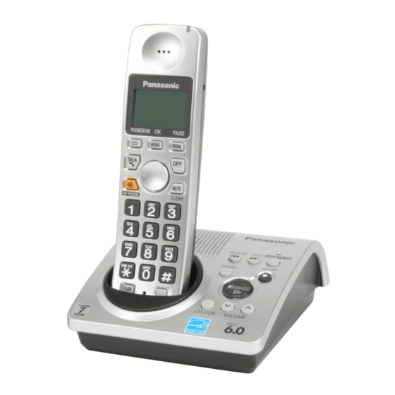
Table of Contents
Advertisement
Advertisement
Table of Contents
Troubleshooting

Summarization of Contents
Safety Precaution
For Service Technicians
Precautions for handling ICs and LSIs to prevent static electricity damage during repair.
Technical Descriptions
Block Diagram (Base Unit)
Overview of the Base Unit's internal components and their interconnections.
Circuit Operation (Base Unit)
Detailed explanation of the Base Unit's functional blocks and IC operations.
Block Diagram (Handset)
Overview of the Handset's internal components and their interconnections.
Installation Instructions
Setting up the Base Unit
Instructions for connecting the AC adaptor and telephone line cord to the base unit.
Operation Instructions
Programmable Settings
Guide on customizing unit functions and settings via the handset display menu.
Registering a Handset
Step-by-step guide to register a handset to the base unit.
Troubleshooting Guide
Troubleshooting Flowchart
A visual guide to diagnose and resolve common unit operational issues.
How to Replace the Flat Package IC
Detailed steps and precautions for replacing surface-mount ICs on PCBs.
Disassembly and Assembly Instructions
Disassembly Instructions
Procedures for safely taking apart the base unit for inspection or repair.
Measurements and Adjustments
The Setting Method of JIG (Base Unit)
Instructions for setting up test equipment (JIG) for base unit measurements.
Schematic Diagram
Schematic Diagram (Base Unit_Main)
Main schematic diagram detailing the Base Unit's electronic circuit layout.
Printed Circuit Board
Circuit Board (Base Unit_Main)
Component layout view of the main Base Unit printed circuit board.
Appendix Information of Schematic Diagram
CPU Data (Base Unit)
Pin data and functions for the Base Unit's CPU (BBIC).
Exploded View and Replacement Parts List
Replacement Part List
List of part numbers and descriptions for replacing components.


Need help?
Do you have a question about the KX-TGA101B and is the answer not in the manual?
Questions and answers