Table of Contents
Advertisement
Quick Links
READ AND FOLLOW ALL INSTALL
FAILURE TO DO SO MAY RESULT IN PERSONAL INJURY OR PROPERTY DAMAGE!
•
Install only on a properly operating and balanced door. A door that is operating improperly could cause severe
injury. Before installing the operator, have qualified service personnel make repairs to cables, and other hardware.
•
Before installing the operator, remove or make inoperative, all locks (unless mechanically and/or electrically
interlocked to the power unit), all activation units and accessories that may be connected to the door.
•
A commercial/industrial door operator that has exposed moving parts capable of causing injury to persons or
employs a motor deemed indirectly accessible by virtue of its location above the floor shall include:
- Install the door operator at least 2.4 m (8ft) or more above the floor, and/or
- If the operator must be installed less than 2.4 m (8ft) above the floor, then exposed moving parts must be
protected by covers or guarding provided by the operator manufacturer.
•
The control unit MUST be located: (1) within the sight of the door, and (2) at a minimum height of 1.5 m (5ft) above
the floors, landings, steps, or any other adjacent walking surface and (3) away from all moving parts of the door.
•
Install the Entrapment Warning Placard next to the control station in a prominent location if applicable.
•
To reduce the risk of injury to persons - Use this system only with pedestrian doors.
•
Do not connect the operator to a power supply until instructed to do so. Connection of the high voltage supply
should be done by a qualified professional and within the guidelines of the enforced local electrical codes.
•
HIGH VOLTAGE (INCOMING 115 VAC) WIRES AND LOW VOLTAGE WIRES CANNOT SHARE THE SAME
ACCESS HOLE. HIGH VOLTAGE WIRES MUST BE ROUTED AND SECURED AWAY FROM ALL LOW
VOLTAGE WIRES.
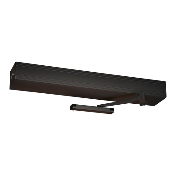
DITEC HA8-LP LOW ENERGY
SWING OPERATOR
Installation & Instruction Manual
Entrematic Canada Inc.
Toll Free: 1-877-348-6837
info.ditec.ca@entrematic.com
www.ditecentrematic.ca
A
ATION INSTRUCTIONS CAREFULLY!
Entrematic USA Inc.
Toll Free: 1-866-901-4284
info.ditec.us@entrematic.com
www.ditecentrematic.us
HA8-LP Manual V. 5.0
Advertisement
Table of Contents

Related Manuals for DITEC entrematic HA8-SP


Summarization of Contents
Before Installation
Replacement Parts
Lists all available replacement parts for the HA8-LP operator.
General Information
Provides overview of the HA8-LP operator, safety, and installation notes.
Technical Specifications & Required Tools
Details product specs, dimensions, power, and necessary installation tools.
Door Handings
Explains different operator handing configurations for push and pull applications.
Consideration of Surroundings
Covers ADA requirements, external factors affecting installation, and door conditions.
Electrical
Details electrical connections, wiring requirements, and safety precautions for installation.
Operator Installation
Pre-Mounting Header Box Instructions
Guides on disassembling and preparing the header box before mounting.
Operator Layout and Handing
Illustrates horizontal and vertical sections for push and pull header configurations.
Handing Modification
Step-by-step instructions for changing the operator's handing from left to right or vice versa.
Double Egress Header
Details installation for double egress operators, including header mounting and arm configuration.
Control Board and Gearbox Installation
Explains how to mount the control board and gearbox onto the header back plate.
Connect Motor Wire Leads
Instructions for connecting motor and back check/latch wire leads to the control board.
Arm Installation
Arm Components & Configurations
Describes main arm components and two available configurations for push arm installation.
Push Arm Installation
Step-by-step guide for installing the push arm, including door shoe and main handle assembly.
Pull Arm (Z-arm) Installation
Detailed steps for fitting and adjusting the pull arm (Z-arm) for proper door operation.
Universal Arm
Instructions for using the universal arm in both push and pull applications for flexibility.
Operator Tuning
Back Check and Latch Adjustment
Guides on setting back check and latch positions using proximity switches.
Spring Tension Adjustment
Explains how to increase or decrease spring tension for windy conditions and latch pressure.
Testing with Obstruction
Testing with Obstruction
Details procedures for testing the operator's response to obstructions and adjusting overload.
Door Operating Mode
Basic Operation
Describes the standard opening and closing sequence of the operator.
Operation Switch
Explains the function of the 3-position switch (Automatic, Hold Open, OFF).
Control Board Setting
Digital Board Diagram
Illustrates the layout of the digital control board with key components.
Digital Board Wiring
Provides wiring diagrams for connecting sensors, switches, and power to the control board.
Digital Board Specification
Details input/output specifications and transformer compatibility for the digital board.
Control Board Programming
Programming Specification (Digital Board)
Outlines the process for programming the digital control board using switches and LEDs.
Safety Monitoring
Explains how to enable and configure safety monitoring features for sensors.
Safety Sensor Connection - BEA Bodyguard
Provides wiring instructions for connecting BEA Bodyguard sensors to the control board.
Safety Sensor Connection - BEA Superscan
Details wiring for BEA Superscan sensors, including monitoring setup.
Safety Sensor Connection - Optex OA-FLEX
Wiring guide for Optex OA-FLEX sensors, including important setup notes.
Dual Board & Programming
Dual Door Digital Board Specification (Fully Automatic only)
Specifies inputs, outputs, and features for dual door automatic operation.
Wiring Diagram
Shows the complete wiring diagram for dual door control with safety monitoring.
Programming Specification
Details programming parameters for dual door operation, including speeds and delays.
ADA Adjustments
Adjustments for ADA
Covers ADA compliance adjustments for opening speed, closing, and overload detection.
Installation Wrap Up
Additional Components: Sensor(s) / Knowing Act Devices
Discusses installation of safety sensors, activation devices, and electric strikes.
Header Cover Installation
Instructions for installing the header face cover after all adjustments are complete.
Safety Decals
Guidance on applying safety decals to the door according to ANSI standards.
Need help?
Do you have a question about the entrematic HA8-SP and is the answer not in the manual?
Questions and answers