Table of Contents
Advertisement
Quick Links
Advertisement
Chapters
Table of Contents

Related Manuals for Xtralis VEP-1


Summarization of Contents
VESDA Student Workbook
DOCUMENT HISTORY
Records changes made to the document over different revisions.
VESDA Course Overview
Provides an overview of the VESDA course content and learning objectives.
Learning outcomes
Details the skills and knowledge participants will gain upon course completion.
Audio controls
Explains how to manage audio settings within the Zoom meeting interface.
Video controls
Details how to manage video settings, including starting and stopping the camera.
Chat
Describes the functionality of the chat feature for communication during the webinar.
Share Screen
Explains how to share computer screens or applications during the webinar.
Reactions
Covers the use of reaction icons to provide feedback to the instructor.
Leave the meeting
Provides instructions on how to exit the virtual meeting.
Introductions
Section dedicated to participant introductions at the beginning of the session.
VESDA certification
Outlines the requirements to obtain official VESDA certification.
Webinar best practices
Offers recommendations for an optimal webinar experience.
Webinar prerequisites
Lists the necessary steps and resources required before attending the webinar.
Create Xtralis Account
Instructions on how to create an account on the Xtralis platform.
Sign In or Register
Guide for signing into an existing Xtralis account or registering a new one.
Download documentation
Instructions on how to find and download necessary documentation.
Technical support
Provides contact information for technical support.
VESDA Products
Advanced Smoke Detection (ASD)
Introduction to Aspirating Smoke Detection technology and its benefits.
RSET vs. ASET
Comparison of Required Safe Egress Time (RSET) and Available Safe Egress Time (ASET).
ASD technology advantages
Highlights the benefits of Aspirating Smoke Detection (ASD) technology.
VESDA model comparison chart
Compares features and specifications across different VESDA detector models.
Worldwide certifications
Lists the global certifications and quality standards held by VESDA products.
Why VESDA-E?
Explains the advantages and applications of the VESDA-E series.
Business continuity is paramount
Discusses how VESDA-E solutions ensure business continuity by minimizing downtime.
Smoke can be difficult to detect
Addresses challenges in detecting smoke in various environments and VESDA-E solutions.
Environments influence effective detection
Explains how environmental factors affect detection and VESDA-E solutions.
Evacuation is a challenge
Discusses evacuation challenges and how VESDA-E aids in safe evacuation.
Discreet detection is required
Covers scenarios requiring discreet smoke detection and VESDA-E solutions.
Maintenance access is difficult
Addresses challenges with maintenance access and VESDA-E solutions.
Suppression System pairing
Explains how VESDA-E systems pair with suppression systems for effective fire control.
Healthcare
Details VESDA detector suitability for healthcare environments.
Data Centers & communication infrastructure
Discusses VESDA applications in data centers and communication infrastructure.
Industrial facilities
Covers VESDA detector suitability for various industrial facility applications.
Solutions for all environments
Highlights VESDA's versatility across diverse environmental conditions.
Detectors
Overview of different types of VESDA detectors available.
VESDA VLF
Details on the VESDA VLF model, its features and applications.
VESDA VLI
Information on the VESDA VLI model, its features and reliability.
VLI reliability
Explains the key components contributing to VESDA VLI reliability.
VESDA E-Series
Overview of the VESDA E-Series product line.
VESDA VEU
Details on the VESDA VEU model, its features and internal components.
Internal components
Describes the internal structure and components of VESDA detectors.
VESDA VEP (4 Pipes)
Information on the VESDA VEP (4 Pipes) model specifications.
VESDA VEP-A00-1P
Details on the VESDA VEP-A00-1P model specifications.
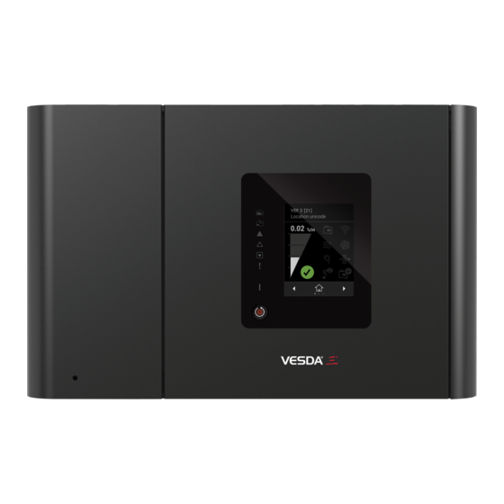
Front panel display
Explains the functionality of the detector's front panel display.
3.5 inch touch screen features
Details the features and operation of the 3.5-inch touch screen interface.
VESDA VEA
Overview of the VESDA VEA detector and its capabilities.
VESDA VEA sample point fittings
Information on sample point fittings for VESDA VEA detectors.
VEA 3.5 inch display
Description of the VEA detector's 3.5-inch display screens.
Hybrid solution
Discusses the hybrid solution approach in VESDA systems.
Operation (monitoring state)
Explains the normal monitoring operation of VESDA detectors.
Operation (smoke event)
Describes the detector's operation during a smoke event.
Internal (smoke event)
Details the internal processes of the detector during a smoke event.
Operation (auto cleaning)
Explains the auto-cleaning function of the VESDA detector.
Operation (end to end supervision)
Describes the end-to-end supervision capabilities of the system.
Centralized smoke testing
Covers the process of centralized smoke testing for VESDA systems.
VEA tubes
Information on the types of VEA tubes used in the system.
Sample points
Details on the types and placement of sample points.
Tube Fittings
Overview of various tube fittings used in VESDA pipe networks.
Installation
Learning outcomes
Defines the learning objectives for the installation module.
Pre-installation
Steps and documents required before starting the installation process.
Original CAD drawing
Reference to the original CAD drawings for installation planning.
FLAG NOTES
Important notes and specifications related to the installation flag points.
Isometric drawing
Visual representation of the pipe network layout.
IDP
Installation Data Pack (IDP) details for the installation process.
Installation Practices
Guidelines and best practices for installing VESDA systems.
Detector location
Criteria and considerations for selecting the optimal detector installation location.
Position the mounting bracket
Instructions on how to correctly position and install the mounting bracket.
Secure detector to the mounting bracket
Steps for securely attaching the detector to the mounting bracket.
Detector mounting
Guidance on the physical mounting process of the detector.
Detector installation
Visual examples of correctly installed detectors.
Power supplies
Information on acceptable power supplies for VESDA detectors.
Cabling installation
Guidelines for neat and traceable cabling installation.
Pre-installation checklist
A checklist of tasks to complete before starting the installation.
Pipes and fittings
Information on recommended pipes and fittings for VESDA systems.
Pipe cutter
Guidance on the correct usage of pipe cutting tools.
Bends and clips
Information on recommended bends and pipe clips for installation.
Capillary sampling
Guidelines and applications for capillary sampling methods.
Sampling points
Instructions on drilling and labeling sampling points.
Straight pipe at detector entry
Requirements for straight pipe length before detector entry.
Glue joints
Instructions on the proper application of solvent cement for pipe joints.
Considerations
Key considerations for pipe network installation.
VEA Tubes and Sample Points
Overview of VEA tubes and sample point configurations.
VEA (recommended sample point fittings)
Details on recommended sample point fittings for VEA detectors.
VEA tubes and sample points
Information on VEA tube types and sample point arrangements.
Tube Fittings
Overview of various tube fittings used in VESDA pipe networks.
VESDAnet Connection
VESDAnet technical features
Highlights the technical features and capabilities of VESDAnet.
VESDAnet
Explains the functionality and architecture of the VESDAnet communication network.
Network with High Level Interface (HLI)
Describes networking VESDA systems with High Level Interface (HLI).
Connection options
Outlines different options for connecting VESDA detectors to networks.
VESDAnet
Details how VESDA detectors report alarms and faults via VESDAnet.
Remote modules and sub-racks
Information on remote modules and sub-racks used in VESDA systems.
Connecting to VESDA detectors
Provides instructions on how to connect to various VESDA detector models.
Detector connections
Details on the physical and electrical connections for detectors.
VSC Software Overview
VSC software
Introduction to VSC software for configuring, commissioning, and maintaining VESDA products.
Computer requirements
Specifies the minimum hardware and software requirements for VSC.
Logon Password
Lists default users and passwords for accessing VESDA devices via VSC.
Connection Password
Details on setting and rules for connection passwords in VSC.
VSC Menu Bar
Overview of the main menu bar options within the VSC software.
File menu
Explains the functions available in the File menu of VSC.
Edit menu
Details the functions available in the Edit menu of VSC.
Insert menu
Describes how to insert devices into a project within VSC.
View menu
Explains the View menu options for customizing the VSC interface.
Options
Covers the software preferences and settings available in VSC.
Device View
Details on navigating and customizing the Device View in VSC.
Device
Explains device-specific commands and configurations available in VSC.
Connection
Describes managing and establishing connections to VESDA detectors in VSC.
Help
Information on accessing help resources and support within VSC.
VSC Toolbars
Overview of the various toolbars available in the VSC software.
Main Toolbar
Details the functions of the main toolbar buttons in VSC.
Active Event List Toolbar
Explains the toolbar for managing the active event list in VSC.
Event Log Toolbar
Covers the toolbar functions for the event log view in VSC.
Grid Toolbar
Details the toolbar for managing grid display styles in VSC.
Trend Graph Toolbar
Explains the toolbar options for the trend graph view in VSC.
Alarm Status
Describes how to view and manage the alarm status of detectors in VSC.
Reset
Instructions on how to reset alarms and latching troubles in VSC.
Disable
How to disable detector relays from activating in VSC.
Silence
Steps to silence detector audibles within VSC.
Summary Status
Displays a summary of device status, smoke levels, airflow, and filter usage.
Detail Status
Provides detailed status information including obscuration, airflow, and raw flow.
Version Info
Shows version information for device serial, comms, chamber, and display.
Add a USB VESDAnet Connection
Step-by-step guide to adding a USB connection to VESDAnet.
Add a connection
Instructions for adding a new connection in the VSC software.
Activity
Practical exercise for adding an Ethernet/WiFi VESDAnet connection.
ASPIRE Software
ASPIRE software
Introduction to ASPIRE software for pipe network design and calculation.
Designing and codes
Discusses design principles and compliance with relevant codes and standards.
Designing, codes, and sensitivity classification
Covers design considerations, codes, and sensitivity classifications for ASPIRE.
Launch ASPIRE33 Software
Instructions on how to launch the ASPIRE33 software.
ASPIRE software
Overview of the ASPIRE software interface, including menus and toolbars.
DESIGN Point of View (POV)
Explains the design perspective within the ASPIRE software.
Set Preferences
Guide on setting up software preferences in ASPIRE.
Set preferences
Details on configuring system, units, and language settings in ASPIRE.
Exit ASPIRE software
Instructions on how to properly exit the ASPIRE software.
Activity
Practical exercise for setting ASPIRE preferences.
Rename project
Steps to rename a project within the ASPIRE software.
Add a detector
Instructions for adding a new detector to an ASPIRE project.
Add a pipe
Guide on adding pipe segments to a detector in ASPIRE.
Copy a pipe
Steps for copying and pasting pipe configurations in ASPIRE.
Calculation reminder
Guidance on interpreting calculation results in ASPIRE.
Flow calculation and column headers
Explanation of flow calculation results and column headers in ASPIRE.
Active 3D view
Description of the active 3D visualization of the pipe network in ASPIRE.
Exploring the enlarged 3D view
Guidance on navigating and interacting with the enlarged 3D view in ASPIRE.
Annotation
Details on adding annotations to pipe network designs in ASPIRE.
Activity
Practical exercise for project configuration in ASPIRE.
Copy detector
Steps for copying and renaming detector configurations in ASPIRE.
Two grille coverage using one detector
Guidance on designing for two grille coverage with a single detector in ASPIRE.
Close the Endcap
Instructions for closing the endcap in the ASPIRE pipe network design.
Delete 90° bend
Steps to delete a 90-degree bend from the pipe network in ASPIRE.
Set Relative Distance values
Guidance on setting relative distance values for pipe segments in ASPIRE.
Activity
Practical exercise for creating a two-grille pipe network in ASPIRE.
Adding unions to angle pipe into airflow
Explains the use of unions for proper airflow angle in pipe installations.
Sampling methods - return air grille
Details on sampling methods for return air grilles.
Sampling Point Sensitivity
Covers setting sampling point sensitivity parameters in ASPIRE.
Hole sensitivity vs. detector sensitivity
Compares hole sensitivity against detector sensitivity in ASPIRE.
Computing the Fire 2 Release Point
Explains the calculation for determining the Fire 2 release point in ASPIRE.
Hole Sensitivity vs Detector Sensitivity
Visualizes the relationship between hole and detector sensitivity in ASPIRE.
Create a Computer Room Floor Pipe Network
Instructions for creating a pipe network for computer room floors in ASPIRE.
Computer Room Floor pipe dimensions
Details the dimensions and layout for computer room floor pipe networks.
Activity
Practical exercise for creating a computer room ceiling pipe network in ASPIRE.
Create a Computer Room Ceiling Pipe Network
Steps for designing a pipe network for computer room ceilings in ASPIRE.
Isometric Ceiling Pipe Network
Isometric view of a ceiling pipe network design in ASPIRE.
Original CAD drawing
Reference to original CAD drawings for ceiling pipe network design.
Create a Four Air Handler Unit
Instructions for designing a pipe network for four air handler units in ASPIRE.
4 Air Handler Unit (AHU)
Overview of the design for four Air Handler Units (AHU) in ASPIRE.
4 AHU design
Detailed steps for designing pipe networks for four AHUs in ASPIRE.
Activity
Practical exercise for creating a 4 AHU design in ASPIRE.
Create a Computer Room AC Unit
Instructions for designing a pipe network for a computer room AC unit in ASPIRE.
Computer Room AC Unit
Details of the pipe network design for a computer room AC unit.
VES Scanner
Introduction to the VES scanner functionality in ASPIRE.
VESDA VES scanner
Overview of the VESDA VES scanner, its ports, and operation modes.
VES Scan vs Non-scan modes (Non-Scan)
Explanation of the Non-Scan mode for VESDA scanner analysis.
VES Scanning vs Non-Scan Mode (Scan)
Details on the Scan mode for VESDA scanner analysis, focusing on sensitivity.
Create a Dry Storage Warehouse
Instructions for designing a pipe network for a dry storage warehouse in ASPIRE.
Dry Storage Warehouse
Details of the pipe network design for a dry storage warehouse.
Activity
Practical exercise for creating a dry storage warehouse design in ASPIRE.
Print Documents for System Installation
Guide on printing system installation documents like IDP and BOM.
Generate Installation Data Pack (IDP)
Steps for generating the Installation Data Pack (IDP) in ASPIRE.
Generate IDP
Process for generating the Installation Data Pack (IDP) and closing the window.
Generate BOM
Instructions for generating the Bill of Materials (BOM) in ASPIRE.
Generate Commissioning Report
Steps for generating the commissioning report in ASPIRE.
Activity
Practical exercise for printing system installation documents.
Commission a System
Commissioning
Overview of the VESDA system commissioning process.
1) Pre-Commissioning (before site)
Tasks to perform before visiting the customer site for commissioning.
2) Pre-Commissioning (at site)
On-site tasks including cable checks, power up, and preliminary system checks.
3) Configuration and thresholds
Steps for configuring the system and setting operational thresholds.
4) System tests
Details on various system tests, including relay and performance tests.
Commissioning VEA overview
Overview of the commissioning process for VESDA VEA detectors.
Commissioning VEA
Specific steps for commissioning VESDA VEA detectors, including tube flow scans.
5) Hand Over
Process for handing over the commissioned system to the customer.
References
List of reference materials for troubleshooting and maintenance.
Troubleshooting references
Resources for troubleshooting VESDA systems, including guides and help files.
Maintenance
Recommended maintenance schedule and checks for VESDA systems.
Filter life based on background smoke levels
Guidance on filter replacement intervals based on environmental smoke levels.
Activity
Practical exercise for creating a logo by completing a pipe network drawing.
VESDA Post Webinar Assessment
Instructions for accessing and completing the VESDA Post Webinar Assessment.
Login to Edwards Learning Center
Steps to log into the Edwards Learning Center portal.
Complete the VESDA Post Webinar Assessment
Guide on entering the correct password to start the post webinar assessment.
Type the password
Instructions on entering the specific password to unlock the assessment.
Launch the VESDA Post Webinar Assessment
Steps to launch the VESDA Post Webinar Assessment course.
Start Assessment
Instructions on how to begin the VESDA Post Webinar Assessment.
Complete Assessment
Details on completing the assessment and obtaining a passing score.
To obtain your course certificate
Steps to access and print your course certificate after passing.
Appendix A
VSC Software Installation
Step-by-step guide for installing the VSC software.
VSC Software Installation
Instructions for accepting the license agreement and installing VSC.
VSC Software Installation
Final steps for completing the VSC software installation.
Appendix B
ASPIRE Software Installation
Guide for installing the ASPIRE software.
Software installation
Steps for selecting language and proceeding with ASPIRE installation.
Software installation
Instructions for accepting the license agreement and selecting the installation folder.
Software installation
Steps for configuring shortcuts and starting the ASPIRE installation.
Software installation
Final steps for completing the ASPIRE software installation.
VESDA Checklist r8
1. Add a USB VESDAnet connection
Checklist item for establishing a USB VESDAnet connection.
2. Copy and Paste 12 CONN files
Checklist item for copying and pasting CONN files.
3. Connect and View
Checklist item for connecting to and viewing VESDA devices.
4. Logon
Checklist item for logging into the VESDA system.
5. Set Options
Checklist item for setting system options and regional preferences.
6. Set System Date and Time
Checklist item for setting the system date and time.
7. Configure a Detector
Checklist item for configuring detector settings in VSC.
8. Normalize Air Flow
Checklist item for normalizing air flow in VESDA detectors.
9. Air Flow Fault Test
Checklist item for performing an air flow fault test.
10. Go to Standby
Checklist item for placing a detector into standby mode.
11. View Event Log
Checklist item for viewing the event log of VESDA detectors.
12. Save Data
Checklist item for saving system data.
13. Print Device Report
Checklist item for printing device reports.
14. Set ASPIRE Preferences
Checklist item for setting ASPIRE software preferences.
15. Project Configuration
Checklist item for configuring a project in ASPIRE.
16. Create a Two Grilles Pipe Network
Checklist item for creating a two-grille pipe network in ASPIRE.
17. Create Sampling Point Sensitivity for Two Grille Detector
Checklist item for setting sampling point sensitivity in ASPIRE.
18. Create a Computer Room Floor Pipe Network
Checklist item for creating a computer room floor pipe network in ASPIRE.
19. Create a Computer Room Ceiling Pipe Network
Checklist item for creating a computer room ceiling pipe network in ASPIRE.
20. Create a 4 AHU design
Checklist item for creating a 4 AHU design in ASPIRE.
21. Create a Computer Room AC Unit (CRAC)
Checklist item for creating a CRAC pipe network in ASPIRE.
22. Create a Dry Storage Warehouse
Checklist item for creating a dry storage warehouse pipe network in ASPIRE.
23. Print Documents for System Installation
Checklist item for printing system installation documents.
24. Set Smoke Thresholds
Checklist item for setting smoke thresholds in VSC.
25. Test Transport Time
Checklist item for testing transport time.
26. Create a logo
Checklist item for creating a logo using pipe network drawing.
VESDA Pipe Network Design Guide
Intellectual Property and Copyright
Legal information regarding document usage and copyright.
Disclaimer
Legal disclaimer about the document's content and warranty.
General Warning
Important safety warnings related to product installation and use.
Scope
Overview of the VESDA Pipe Network Design Guide's purpose and content.
Document Conventions
Explanation of typographic conventions and icons used in the document.
Contact Us
Contact information for different regions.
Codes and Standards Information for Air Sampling Smoke Detection
Information on relevant codes and standards for smoke detection systems.
1 Introduction to Good Design
Introduction to the principles of good design for VESDA pipe networks.
1.1 Introduction to Pipe Network Design
Explains the fundamental concepts of VESDA air sampling pipe networks.
1.2 Before You Start
Key considerations and requirements before starting pipe network design.
2 Designing a Pipe Network
Outlines the steps involved in designing an effective VESDA pipe network.
3 Gather Site Information
Essential steps for gathering site-specific information for pipe network design.
3.1 Site Layout and Measurements
Importance of site layout knowledge for planning fire zones and pipe networks.
3.2 Regulatory Requirements
Consideration of local codes and standards for fire zones and pipe network design.
3.3 Air Flow
Determining airflow within the protected area for effective pipe network design.
3.4 Ambient Conditions
Identifying ambient conditions that may affect VESDA system efficiency.
3.5 Purpose of the Site
Considering the site's purpose and potential smoke sources for design.
3.6 Site Construction
Factors related to site construction that influence pipe network installation.
3.7 Surrounding Environment
Assessing the surrounding environment for potential smoke or pollutant impacts.
4 Air Sampling Methods
Overview of different air sampling methods for VESDA systems.
4.1 Standard Pipe Sampling
Guidelines for standard pipe sampling methods in VESDA installations.
4.2 Capillary Tube Sampling
Guidelines for using capillary tubes for sampling air from enclosed areas.
4.3 Open Area Protection
Methods for protecting open areas using VESDA sampling techniques.
4.4 Return Area Protection
Strategies for protecting return air areas with VESDA sampling.
4.5 Object Protection
Methods for protecting specific objects or equipment using VESDA sampling.
4.6 In-duct Sampling
Guidelines for sampling air from within ducts for fire detection.
4.7 Large Area Sampling
Techniques for sampling air in large areas with high ceilings.
4.8 Dilution
Explains the effect of smoke dilution in air samples and its impact.
4.9 Cumulative Sampling
Discusses how VESDA systems aggregate smoke detection from multiple points.
4.10 Reference Sampling
Method for compensating for background smoke using a reference detector.
4.11 Sampling Methods for Different Applications
Table summarizing sampling methods suitable for various applications.
4.12 Additional Monitoring Equipment
Information on using additional equipment like VESDA ECO for gas detection.
5 Defining the Site
Key factors to consider when defining site parameters for VESDA design.
5.1 Regulatory Requirements
Understanding regulatory requirements for pipe spacing and sampling points.
5.2 Fire Zones and VESDA Addresses
Creating fire zones and assigning VESDA addresses for optimal monitoring.
6 Plan and Map a Pipe Network
Steps for planning and mapping the VESDA pipe network layout.
6.1 Grid Overlay
Using grid overlay techniques to map pipe layout and sampling hole positions.
6.1.1 Sampling Hole Conventions
Conventions for plotting sampling holes based on NFPA 72 requirements.
6.2 Detector Parameters
Comparison of parameters for different VESDA detector models.
6.3 Site Parameters
Factors related to the site that influence pipe network design.
6.4 Client Parameters
Client-specific requirements that should be incorporated into the design.
6.5 Performance Based Parameters
Using performance-based design principles for fire protection systems.
7 Choice of Detector
Guidance on selecting the appropriate VESDA detector based on site conditions.
8 Designing Pipe Networks for Specific Applications
Tailoring pipe network designs for specific applications.
8.1 Standard Rooms
Pipe network design for standard rooms using on-ceiling sampling.
8.2 High Air Exchange Rooms
Sampling methods for high air movement areas, including return and open area sampling.
8.3 Localized Detection
Methods for monitoring specific objects within cabinets or racks.
8.4 High Ceiling
Addressing stratification effects in high ceiling areas with vertical sampling pipes.
9 Testing Design Performance
Methods for testing pipe network design performance using ASPIRE2 software.
9.1 Hole Balance
Understanding and achieving hole balance for optimal VESDA system performance.
9.2 Maximum Transport Time
Measuring and optimizing the maximum transport time for smoke samples.
9.3 Hole Sensitivity
Calculating and interpreting relative sample hole sensitivity.
10 Advantages of Multi Pipe Systems
Benefits of using shorter, multiple pipes for improved network efficiency.
10.1 System Performance Graph
Illustrates system performance variations based on pipe configuration.
10.2 Sampling and End Cap Holes
Guidelines for drilling and placing sampling and end cap holes.
10.3 Pipe Connections
Instructions on pipe joints, bends, tees, Y-pieces, and J-pieces.
11 Recording Pipe Network Design Specifications
Importance of recording pipe network design specifications and modifications.
VESDA Pipe Network Installation Guide
Intellectual Property and Copyright
Legal information regarding document usage and copyright.
Disclaimer
Legal disclaimer about the document's content and warranty.
General Warning
Important safety warnings related to product installation and use.
Scope
Overview of the VESDA Pipe Network Installation Guide's purpose and content.
Document Conventions
Explanation of typographic conventions and icons used in the document.
Contact Us
Contact information for different regions.
Codes and Standards Information for Air Sampling Smoke Detection
Information on relevant codes and standards for smoke detection systems.
1 Introduction
Introduction to the VESDA system and pipe network installation.
1.1 Pipe Network
Explains the function of VESDA air sampling pipe networks.
2 Installation Steps
Basic sequence of steps for installing a VESDA pipe network.
2.1 Pipe Network Installation
Details the normal procedure for installing a VESDA pipe network.
3 Components of a Pipe Network
Describes various components used in constructing a VESDA pipe network.
3.1 Pipe Line
Information on the standard PVC pipe used for VESDA networks.
3.2 Couplings, Socket Unions and Expansion Joints
Details on components used for connecting pipes and managing expansion.
3.3 Bends and Elbows
Guidance on using bends and elbows for changing pipe direction.
3.4 Tees, Y-Pieces and J-Pieces
Information on using tees, Y-pieces, and J-pieces for branching.
3.5 Reducing Connectors
Details on reducing connectors for attaching capillary tubes and drop pipes.
3.6 Pipe Adaptors
Information on pipe adaptors for connecting imperial pipes to detector inlets.
3.7 Capillary Tubes and Drop Pipes
Guidelines for using capillary tubes and drop pipes for sampling.
3.8 Miniature Sampling Points
Details on conical and flush sampling points for capillary tubes.
3.9 Mounting Fixtures
Overview of common pipe mounting options and fixtures.
3.10 Solvent Cement
Instructions on the use of solvent cement for bonding pipes and accessories.
3.11 Labels
Details on adhesive labels for identifying sampling points and pipes.
4 Working with Pipes
Guidelines for successfully working with pipes during installation.
4.1 Cutting Pipes
Instructions on the correct method for cutting VESDA pipes.
4.2 Joining and Bonding
Guidelines for joining and bonding pipes, ensuring proper fit and seal.
4.3 Cementing Pipes Together
Detailed steps for cementing pipes, emphasizing correct application of cement.
4.4 Mounting
Instructions on mounting pipe networks according to design and ASPIRE specifications.
4.5 Bending Pipes
Guidance on bending pipes, including the use of springs and benders.
4.6 Drilling Sampling Holes
Instructions for drilling sampling holes accurately as per IDP specifications.
4.7 Labelling
Information on using adhesive labels to identify pipes and sampling points.
4.8 Using Capillaries and Drop Pipes
Guidelines for installing and using capillary tubes and drop pipes.
5 Installing Pipe Networks
Instructions for installing pipe networks in common site types.
5.1 Ceilings and Floors
Installation procedures for pipe networks in ceilings and floor voids.
5.1.1 On Ceiling
Steps for installing pipe networks directly onto ceilings.
5.1.2 In-Ceiling Installation
Installation procedures for pipe networks within ceiling voids.
5.1.3 Floor Void Installation
Guidelines for installing pipe networks in underfloor voids.
5.1.4 Inter-beam
Methods for inter-beam sampling in areas with large beams.
5.1.5 Capillary Tubes and Drop Pipes Installation
Installation guidelines for capillary tubes and drop pipes.
5.1.6 Concealed Sampling
Methods for concealed sampling to maintain aesthetics or security.
5.2 Return Air Grilles and Air Ducts
Sampling methods for monitoring return air grilles and air ducts.
5.2.1 Return Air Grilles
Specific installation guidelines for sampling over return air grilles.
5.2.2 Supply Air Sampling
Referral to return air grille or duct designs for supply air sampling.
5.2.3 Duct Sampling and Condensation
Considerations for duct sampling, including condensation and probe installation.
Exhaust probe installation:
Steps for installing the exhaust probe correctly in a duct.
5.3 Cabinet and Rack Detection
Methods for detecting smoke within cabinets and racks.
5.3.1 In-Cabinet Installation
Installation procedures for sampling air from within cabinets.
5.3.2 On-Cabinet
Guidelines for installing sampling pipes directly over cabinets.
5.3.3 In-Rack Installation
Installation procedures for pipe networks in high-bay racking systems.
5.4 Open Spaces
Sampling methods for open spaces, including vertical sampling.
5.4.1 Vertical Sampling Pipe Installation
Steps for installing vertical sampling pipes in areas with high ceilings.
6 Recording Pipe Network Details
Importance of recording pipe network design specifications and modifications.
VESDA Commissioning Guide
Intellectual Property and Copyright
Legal information regarding document usage and copyright.
Disclaimer
Legal disclaimer about the document's content and warranty.
General Warning
Important safety warnings related to product installation and use.
Scope
Overview of the VESDA Commissioning Guide's purpose and content.
Document Conventions
Explanation of typographic conventions and icons used in the document.
Contact Us
Contact information for different regions.
Codes and Standards Information for Air Sampling Smoke Detection
Information on relevant codes and standards for smoke detection systems.
1 Introduction to VESDA Commissioning
Introduction to the final stage of VESDA system installation: commissioning.
2 The Commissioning Process
Step-by-step process for systematically checking and validating VESDA system operations.
Table 2-1: Commissioning process steps
A table outlining the sequential steps required for system commissioning.
3 Pre-Commissioning
Tasks to perform before and during the initial stages of commissioning.
3.1 Before going to the Site
Information gathering and preparation required before visiting the site.
3.2 VESDA Commissioning Form - Prerequisites
Details to be completed in the VESDA commissioning form prior to site visit.
3.3 Once on Site
Tasks to be performed once the commissioning engineer is on site.
3.3.1 Checking Cabling and Initial Powerup
Procedure for checking cabling and performing initial system power-up.
3.3.2 Preliminary Systems Check
Conducting preliminary system checks before commencing commissioning.
4 System Configuration and Setting Thresholds
Steps for configuring system settings and alarm thresholds.
4.1 Generic Configuration (VLC, VLS, VLP)
Generic configuration steps applicable to VLC, VLS, and VLP detectors.
4.2 Detector Specific Configuration Steps (VLC, VLS, VLP)
Detector-specific configuration steps for VLC, VLS, and VLP models.
4.2.1 VESDA VLP Configuration
Specific configuration steps for the VESDA VLP detector.
Setting Air Flows
Procedure for setting air flow parameters for detectors.
Setting Smoke Thresholds
Procedure for setting smoke thresholds and alarm levels for detectors.
Relay Setup
Configuration of relay functions and assignments for VESDA detectors.
4.2.2 VESDA VLS Configuration
Specific configuration steps for the VESDA VLS detector.
4.2.3 VESDA VLC Configuration
Specific configuration steps for the VESDA VLC detector.
4.3 VESDA VFT-15 Detector Configuration
Configuration steps specific to the VESDA VFT-15 detector.
Main Menu Modes
Steps to enter the main menu modes on the detector's display panel.
Access Codes
Explanation of access levels and codes for configuring detectors.
4.3.1 VESDA VFT-15 Detector Programmable Functions
Key programmable functions for the VESDA VFT-15 detector.
Setting Units
Procedure for setting display units (SI or US Imperial) on the detector.
Setting Time and Date
Instructions for setting the time and date on the detector.
Setting IP Address and Mask
Steps for configuring the detector's IP address and subnet mask.
Setting the Modbus Address
Procedure for setting the Modbus address for detector communication.
Setting Air Flows
Configuring air flow parameters like delay, limits, and normalization.
Setting Smoke Thresholds
Setting smoke thresholds for day/night, alarm delays, and change-over times.
Setting GPI Function
Configuring the General Purpose Input (GPI) for reset or isolate functions.
Setting Up I/O Modules
Configuring Input/Output modules included in the detector.
4.4 VESDA VLF Configuration
Information on the configuration of the VESDA VLF detector.
4.5 Documenting Configuration and Thresholds
Guidance on documenting system configuration and thresholds.
5 System Integrity Test
Methods for testing the integrity of the VESDA system.
5.1 Performance-based Smoke Testing
Performing smoke tests to prove pipe network integrity and measure response time.
5.1.1 Testing and Stratification Problems
Addressing stratification issues in high-roof areas during smoke testing.
5.1.2 Pipe Integrity Smoke Testing
Testing the integrity of the sampling pipe network using a smoke source.
5.1.3 Smoke Pellet Testing
Method for testing high and enhanced sensitivity environments using smoke pellets.
5.1.4 Polyurethane Mat Smoke Testing
Using polyurethane mat for smoke testing in open areas.
5.1.5 Wire Burn Smoke Testing
Method for simulating early fire stages using wire burn tests.
5.2 Testing Relay Function
Testing the on/off function of relays using LCD Programmer or VSC Software.
5.3 Testing Devices
Performing diagnostic tests on VESDA detectors using LCD Programmer or VSC.
5.4 Documenting Test Results
Recording test results on VESDA commissioning forms.
6 Hand Over
Process for handing over the commissioned VESDA system to the client.
Need help?
Do you have a question about the VEP-1 and is the answer not in the manual?
Questions and answers