Table of Contents
Advertisement
Quick Links
Advertisement
Table of Contents

Related Manuals for Milesight UC1114


Summary of Contents for Milesight UC1114
- Page 1 LoRaWAN Controller ® UC11 Series User Guide Milesight IoT...
- Page 2 The device must never be subjected to shocks or impacts. Declaration of Conformity UC11 series is in conformity with the essential requirements and other relevant provisions of the CE, FCC, and RoHS. Copyright © 2011-2021 Milesight. All rights reserved.
- Page 3 Revision History Date Doc Version Description Oct. 13, 2021 V 1.0 Initial version...
-
Page 4: Table Of Contents
4.3.1 Basic Settings........................14 4.3.2 DI/DO Settings........................14 4.3.3 AI Settings...........................15 4.3.4 RS485 Settings........................15 4.3.5 RS232 Settings........................18 4.4 IF-THEN Command........................19 4.5 Maintenance..........................21 4.5.1 Upgrade..........................21 4.5.2 Reset to Factory Default....................21 5. Milesight IoT Cloud Management......................22 6. Device Payload............................23... -
Page 5: Product Introduction
Industrial metal case design with with operating temperature range Compliant with standard LoRaWAN ® gateways and network servers Quick and easy management with Milesight IoT Cloud solution 2. Hardware Introduction 2.1 Packing List 1 × UC11 Series 1 × LoRa 1 ×... -
Page 6: Hardware Overview
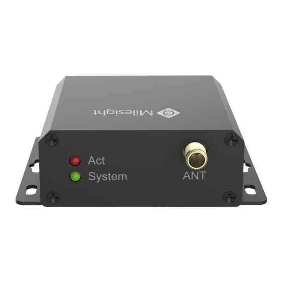
2.2 Hardware Overview A. Front Panel LED Indicator Area SYSTEM: System Indicator ACT: Network Status Indicator LoRa Antenna Connector Micro USB Port B. Rear Panel Data Interfaces & Power Interface Model UC1114 UC1122 UC1152 Definition Description Definition Description Definition Description Ground Ground Ground... -
Page 7: Led Indicators
2.3 LED Indicators Indication Status Description Static System Start-up System System Status On for 500 ms, off for 500 ms The system is running properly On for 200 ms, off for 200 ms The system does not connect to server Fails to join the network Network Status On for 500 ms, off for 500 ms... -
Page 8: Power Supply
Analog Input: RS232 & RS485: 3.2 Power Supply UC11 series device support 5-24 VDC power supply. You can use other supplies or power adapter to power on the device. Note: For industrial applications, it’s suggested not to release the metal case and use a... -
Page 9: Antenna Installation
3. Mount the device to the wall by passing the wall mounting screws (M3 * 20) into the device mounting holes. 4. Operation Guide 4.1 Log in the ToolBox 1. Download ToolBox software from Milesight IoT website. 2. Power on the UC11 device, then connect it to computer via micro USB port. - Page 10 3. Open the ToolBox and select type as “General”, then click password to log in ToolBox. (Default password: 123456) 4. After logging in the ToolBox, you can change device settings.
-
Page 11: Lorawan Settings
4.2 LoRaWAN Settings LoRaWAN settings is used for configuring the transmission parameters in LoRaWAN ® network. 1. Go to “LoRaWAN -> Basic” to configure join type, App EUI, App Key and other information. You can also keep all settings by default. Parameters Description Device EUI... - Page 12 1) Please contact sales for device EUI list if there are many units. 2) Please contact sales if you need random App keys before purchase. 3) Select OTAA mode if you use Milesight IoT cloud to manage devices. 4) Only OTAA mode supports rejoin mode.
- Page 13 1-40: Enabling Channel 1 to Channel 40 1-40, 60: Enabling Channel 1 to Channel 40 and Channel 60 All: Enabling all channels Null: Indicates that all channels are disabled 3. Go to “LoRaWAN -> Advanced” to configure advanced settings. You can also keep all values by default.
-
Page 14: Data Interface Settings
Digital Output: Connect devices to corresponding DO ports according to section 3.1, then you can send downlinks to trigger the DO. Pulse Counter: Pulse counter feature only works with UC11 series hardware version 3.0. 1. Connect devices to corresponding DI ports. -
Page 15: Ai Settings
2. Go to “General” page of UC1114 or “General -> Basic” page of UC1122/UC1152, select type as Counter. 3. Click “Start” or “Stop” to make the device start/stop counting. 4. Check current count values by clicking “Refresh”. 5. Click “Clear” to make the device count from 0. Note: 1) UC11xx only starts counting when it detects 6 pulses from pulse devices;... - Page 16 Parameters Description Baud Rate 4800/9600/19200/38400/57600/115200 are available. Data Bit 8 bit is available. Stop Bit 1 bit/2 bit are available. Parity None, Odd and Oven are available. If this mode is enabled, UC1152 will transparent Modbus RTU commands Modbus RS485 from network server to RS485 terminal devices and send Modbus reply bridge LoRaWAN originally back to network server.
- Page 17 Interval The maximum response time that the UC1152 waits for the reply to Max Resp Time the command. If it does not get a response after the max response time, it is determined that the command has timed out. Set the maximum retry times after device fails to read data from Max Retry Time RS485 terminal devices.
-
Page 18: Rs232 Settings
4.3.5 RS232 Settings UC1152 has one RS232 for device transparent communication. 1. Connect RS232 device to RS232 port. 2. Go to “General -> RS232” to enable RS232 and configure serial port settings. Serial port settings should the same as RS232 terminal devices. Parameters Description Baud Rate... -
Page 19: If-Then Command
4.4 IF-THEN Command UC11 series support configuring locally IF-THEN commands to do some actions automatically even without network connection. Besides, you can backup your command settings and import to other devices. 1. Go to “Command” page, click “Read command From Device” to check device command settings. - Page 20 When UC11 device receive a specific message from network server. The NS Received a message hex format is ff12+message length + message content. message Example: set the message content as character “P”, then you need to send message as ff120450.(whole message length is 4 bytes, 50 means “P”). The Device Reboot the device.
-
Page 21: Maintenance
4.5 Maintenance 4.5.1 Upgrade UC11 series support upgrade locally via ToolBox software. 1. Download firmware from www.milesight-iot.com to your PC. 2. Go to “Maintenance -> Upgrade”, click “Browse” to import firmware and upgrade the device. Note: Any operation on ToolBox is not allowed during upgrading, otherwise the upgrading will be interrupted, or even the device will break down. -
Page 22: Milesight Iot Cloud Management
Milesight IoT Cloud. For more info about connecting gateway to cloud please refer to Gateway User Guide. 2. Go to “My Devices” page and click “+New Devices”. Fill in the SN of UC11 series and select associated gateway. -
Page 23: Device Payload
6. Device Payload UC11 Series use the standard Milesight IoT payload format based on IPSO. Please refer to the UC11 Series Communication Protocol; for decoders of Milesight IoT products please click here. -END-...
Need help?
Do you have a question about the UC1114 and is the answer not in the manual?
Questions and answers