Milesight UC50 Series User Manual
Hide thumbs
Also See for UC50 Series:
- User manual (37 pages) ,
- User manual (25 pages) ,
- User manual (35 pages)
Table of Contents
Advertisement
Quick Links
Advertisement
Table of Contents

Related Manuals for Milesight UC50 Series


Summary of Contents for Milesight UC50 Series
- Page 1 UC50x Series User Guide Milesight IoT...
- Page 2 Safety Precautions Milesight will not shoulder responsibility for any loss or damage resulting from not following the instructions of this operating guide. The device must not be remodeled in any way. Do not place the device close to objects with naked flames.
-
Page 3: Table Of Contents
4.3.3 GPIO Settings........................18 4.3.4 AI Settings.......................... 20 4.4 Maintenance..........................22 4.4.1 Upgrade..........................22 4.4.2 Backup..........................23 4.4.3 Reset to Factory Default....................24 5. Milesight IoT Cloud Management......................25 5.1 Add a Milesight Gateway......................25 5.2 Add UC50x to Milesight IoT Cloud.....................26 6. Device Payload............................27... -
Page 4: Product Introduction
Quick wireless configuration via NFC Compliant with standard LoRaWAN ® gateways and network servers Quick and easy management with Milesight IoT Cloud solution 2. Hardware Introduction 2.1 Packing List 1 × U50x Device 2 × Data Cables 1 ×... -
Page 5: Hardware Overview
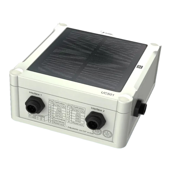
2.2 Hardware Overview UC501 UC502 Data Interface 1: Description 5V/9V/12V(Switchable) 3.3V GPIO1 GPIO2 RS232/RS485(Switchable) Reserved RS232 RS485 Data Interface 2: Description 5V/9V/12V(Switchable) 3.3V Analog Input 1 Analog Input 2 Reserved... -
Page 6: Internal Interfaces
Power Interface (UC501): Description VCC(5-24V) 2.3 Internal Interfaces DIP Switch: Interface DIP Switch 12V: 1 on 2 off 3 off Power Output 9V: 1 off 2 on 3 off 5V: 1 of 2 off 3 on 4-20mA ADC: 1 off 2 on 3 on Analog Input 0-10V ADC: 1 on 2 off 3 off Add 120 Ω... -
Page 7: Dimensions(Mm)
Power Button: Function Action LED Indication Turn On Press and hold the button for more than 3s. Off → On Turn Off Press and hold the button for more than 3s. On -> Off Reset Press and hold the button for more than 10s. Blinks. -
Page 8: Uc50X Installation
3.2 UC50x Installation Wall Mounting Make sure you have wall mounting bracket, bracket mounting screws, wall plugs, wall mounting screws and other required tools. Steps: 1. Mount the enclosure to the mounting bracket with the bracket mounting screws. 2. Align the mounting bracket horizontally to the desired position on the wall, use a marker pen to mark four mounting holes on the wall, and then remove the mounting bracket from the wall. -
Page 9: Operation Guide
Steps: 1. Download and install from Google Play or Apple Store. 2. Enable NFC on the smartphone and open“Milesight ToolBox” APP. 3. Attach the smartphone with NFC area to the device to read basic information. 4. Basic information and settings of devices will be shown on ToolBox if it’s recognized... -
Page 10: Usb Configuration
2) If the smartphone fails to read/write configurations via NFC, keep the phone away and back to try again. 3) UC50x series can also be configured by dedicated NFC reader, which can be purchased from Milesight IoT. 4.1.2 USB Configuration Preparation: Type-C USB cable ... - Page 11 Steps: 1. Download ToolBox from Milesight IoT website. 2. Open the case of UC50x and connect the UC50x to computer via type-C port. 3. Open the ToolBox and select type as “General”, then click password to log in ToolBox. (Default password: 123456) 4.
-
Page 12: Lorawan Settings
4.2 LoRaWAN Settings LoRaWAN settings is used for configuring the transmission parameters in LoRaWAN ® network. Step 1: Go to “LoRaWAN -> Basic” of ToolBox software or “Setting->LoRaWAN Settings” for ToolBox APP to configure join type, App EUI, App Key and other information. You can also keep all settings by default. - Page 13 1) Please contact sales for device EUI list if there are many units. 2) Please contact sales if you need random App keys before purchase. 3) Select OTAA mode if you use Milesight IoT cloud to manage devices. 4) Only OTAA mode supports rejoin mode.
-
Page 14: Interface Settings
Note: For -868M model, default frequency is EU868; For -915M model, default frequency is AU915. 4.3 Interface Settings UC50x series support data collection by multiple interfaces including GPIOs, analog inputs and serial ports. Besides, it can also power the terminal devices by power output interfaces. Basic settings are as follows: Step 1: Go to “General->Basic”... -
Page 15: Rs485 Settings
Interface 1/2 3V3 Enable 3.3V power output. After enabled, the power output will supply Output power continuously. Change the password for ToolBox APP or software to read/write this Change Password device. Step 2: Go to corresponding pages to change GPIO, analog input or serial port settings as following chapters. - Page 16 Stop Bit 1 bit/2 bit are available. Parity None, Odd and Oven are available. Execution Interval The execution interval between each Modbus command. The maximum response time that the UC50x waits for the reply to the Max Resp Time command. If it does not get a response after the max response time, it is determined that the command has timed out.
- Page 17 Step 4: For ToolBox software, click “Fetch” to check if UC50x can read correct data from terminal devices. You can also click “Fetch” on the top of list to fetch all channel data. Note: Please do not click “Fetch” frequently since response time to reply is differ for every terminal device.
-
Page 18: Rs232 Settings
4.3.2 RS232 Settings Step 1: Connect RS232 device to RS232 port on interface 1. If you need UC50x to power this device, please connect the power cable to 5V/9V/12V power output on interface 1. Step 2: Go to “General -> Serial” of ToolBox software or “Setting->Serial Setting” to enable RS232 and configure serial port settings. - Page 19 Step 3: Select GPIO type according to your requirements. Digital Input: detect high or low status of devices; Digital Output: Send voltage signal to trigger devices; Counter: pulse counter. Digital Input: Step 4: Select initial status of digital input. If pull up is selected, falling edge will be triggered; If pull down is selected, rising edge will be triggered.
-
Page 20: Ai Settings
Pulse Counter: Step 4: Select initial status of digital input. If pull up is selected, falling edge will be triggered and increase 1; if pull down is selected, rising edge will be triggered and increase 1. Parameters Description Initial status of counter. Digital Input Pull Down: Increase 1 when detecting rising edge Pull Up/None: Increase 1 when detecting falling edge... - Page 21 Step 3: Select analog input type according to analog device type. Note: Ensure DIP switches has changed before changing “Analog Input Signal Type” to 0-10V. Step 4: Enable “Interface 2(Pin 1) 5V/9V/12V” and configure “Power Output Time Before Collect”, UC50x will power the analog devices for a period of time before collecting data. Note: When you use power output to power analog devices, it only supplies power when reporting interval is coming.
-
Page 22: Maintenance
For ToolBox APP, a. Click “Collect” and attach smart phone to device to make device collect data. b. Click “Fetch” and attach smart phone to make APP read the data. 4.4 Maintenance 4.4.1 Upgrade UC50x series support upgrade locally or over the air only via ToolBox software. Upgrade Locally: Step 1: Click “Browse”... -
Page 23: Backup
4.4.2 Backup UC50x devices support configuration backup for easy and quick device configuration in bulk. Backup is allowed only for devices with the same model and LoRa frequency band. Please select one of following methods to backup device: Via ToolBox Software Step 1: Go to “Maintenance->Backup and Reset”, click “Export”... -
Page 24: Reset To Factory Default
4.4.3 Reset to Factory Default Please select one of following methods to reset device: Via Hardware: Open the case of UC50x and hold on power button more than 10s. Via ToolBox Software: Go to “Maintenance->Backup and Reset” to click “Reset”. Via ToolBox APP: Go to “Device->Reset”... -
Page 25: Milesight Iot Cloud Management
Step 1: Enable “Milesight” type network server and “Milesight IoT Cloud” mode in gateway web GUI. Note: Ensure gateway has accessed the Internet. Step 2: Go to “My Devices” page and click “+New Devices” to add gateway to Milesight IoT Cloud via SN. Gateway will be added under “Gateways” menu. -
Page 26: Add Uc50X To Milesight Iot Cloud
Step 3: Check if gateway is online in Milesight IoT Cloud. 5.2 Add UC50x to Milesight IoT Cloud Step 1: Go to “My Devices” page and click “+New Devices”. Fill in the SN of UC50x and select associated gateway. Step 2: Default working mode of UC50x devices is Class A. If you need to change the mode of and go to “Basic Settings”... -
Page 27: Device Payload
Note: Modbus channel settings should be the same as the configuration in ToolBox. 6. Device Payload UC50x Series use the standard Milesight IoT payload format based on IPSO. Please refer to the UC50x Series Communication Protocol ; for decoders of Milesight IoT products please click here.
Need help?
Do you have a question about the UC50 Series and is the answer not in the manual?
Questions and answers