Milesight UC50 Series User Manual
Lorawan controller
Hide thumbs
Also See for UC50 Series:
- User manual (35 pages) ,
- User manual (25 pages) ,
- User manual (28 pages)
Table of Contents
Advertisement
Quick Links
Advertisement
Table of Contents

Related Manuals for Milesight UC50 Series


Summary of Contents for Milesight UC50 Series
- Page 1 LoRaWAN Controller ® UC50x Series User Guide...
- Page 2 Safety Precautions Milesight will not shoulder responsibility for any loss or damage resulting from not following the instructions of this operating guide. The device must not be remodeled in any way. Do not place the device close to objects with naked flames.
- Page 3 Revision History Date Doc Version Description Dec. 9, 2021 V 2.0 Initial version based on hardware 2.0 June 16, 2022 V 2.1 Update 3.3V power output feature 1. Add RS485 byte order feature Nov. 21, 2022 V 2.2 2. Add GPIO initial counting value modification feature July 7, 2023 V 3.0...
-
Page 4: Table Of Contents
4.5 Data Storage .......................... 29 4.6 Data Retransmission ......................30 4.7 Maintenance .......................... 31 4.7.1 Upgrade ........................31 4.7.2 Backup .........................32 4.7.3 Reset to Factory Default .....................34 5. Installation ............................34 6. Milesight IoT Cloud Management ....................35 7. Device Payload ..........................37... -
Page 5: Product Introduction
Quick wireless configuration via NFC Compliant with standard LoRaWAN ® gateways and network servers Quick and easy management with Milesight IoT Cloud solution Supports multicast for control in bulk 2. Hardware Introduction 2.1 Packing List 1 × UC50x 2 ×... -
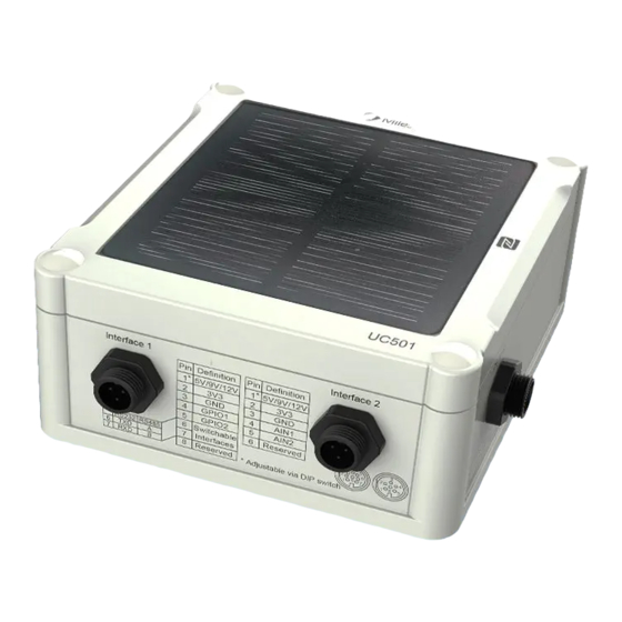
Page 6: Hardware Overview
(EA Version Only) If any of the above items is missing or damaged, please contact your sales Representative. 2.2 Hardware Overview UC501 UC502 UC501(EA Version) UC502 (EA Version) Data Interface 1: Description 5V/9V/12V OUT (Switchable) 3.3V OUT Analog Input 1 Analog Input 2 5-24V DC IN ①②... -
Page 7: Internal Interfaces
Data Interface 2: Description 5V/9V/12V OUT (Switchable) 3.3V OUT GPIO1 GPIO2 RS232/RS485 (Switchable) SDI-12 RS232 RS485 2.3 Internal Interfaces DIP Switch: Interface DIP Switch 12V: 1 on 2 off 3 off Power Output 9V: 1 off 2 on 3 off 5V: 1 off 2 off 3 on 4-20mA ADC: 1 off 2 on 3 on Analog Input... -
Page 8: Dimensions (Mm)
Note: 1) Analog inputs are set to 4-20mA by default, power outputs are set to 12V by default. 2) Power output on interface 1 is used for powering analog devices, power output on interface 2 is used for powering serial port devices and SDI-12 devices. Power Button: Function Action... -
Page 9: Operation Guide
4.1.1 NFC Configuration 1. Download and install Milesight ToolBox App from Google Play or Apple App Store. 2. Enable NFC on the smart phone and launch Milesight ToolBox. 3. Attach the smart phone with NFC area to the device, click NFC read to read device information. -
Page 10: Usb Configuration
Milesight IoT. 4.1.2 USB Configuration 1. Download ToolBox software from Milesight official website. 2. Open the case of UC50x and connect the UC50x to computer via type-C port. 3. Open the ToolBox and select type as General, then click password to log in ToolBox. (Default password: 123456) 4. -
Page 11: Lorawan Settings
4.2 LoRaWAN Settings LoRaWAN settings is used for configuring the transmission parameters in LoRaWAN network. ® 4.2.1 Basic Settings UC50x supports basic configurations like join type, App EUI, App Key and other information. You can also keep all settings by default. - Page 12 Parameters Description Device EUI Unique ID of the device which can also be found on the label. App EUI Default App EUI is 24E124C0002A0001. The port used for sending and receiving data, default port is 85. Application Port Note: RS232 data will be transmitted via another port. UC501: Class A and Class C are available;...
-
Page 13: Frequency Settings
1) Please contact sales for device EUI list if there are many units. 2) Please contact sales if you need random App keys before purchase. 3) Select OTAA mode if you use Milesight IoT cloud to manage devices. 4) Only OTAA mode supports rejoin mode. -
Page 14: Multicast Settings (Uc501 Only)
4.2.3 Multicast Settings (UC501 Only) UC501 supports setting up several multicast groups to receive multicast commands from network servers and users can use this feature to control devices in bulks. 1. Set working mode as Class C. 2. Enable Multicast Group and set a unique multicast address and keys to distinguish other groups. - Page 15 Multicast Group 3: 5572404C696E6B4C6F52613230313825 Multicast Group 4: 5572404C696E6B4C6F52613230313826 3. Add a multicast group on the network server. Take Milesight gateway as an example, go to Network Server > Multicast Groups, and click Add to add a multicast group. Fill in the multicast group information that is the same as device settings, and select the devices that you need to control, then click Save.
-
Page 16: Interface Settings
Note: ensure all devices’ application ports are the same. 4.3 Interface Settings 4.3.1 Basic Settings Parameters Description Reporting interval of transmitting data to network server. Default: 1200s Reporting Interval (20 mins), Range: 10-64800 s. Note: RS232 transmission will not follow the reporting interval. The interval of collecting data when there is an alarm command (see Collection Interval section 4.4). -
Page 17: Analog Input
4.3.2 Analog Input 1. Connect analog device to analog input ports on interface 1. If the analog device requires power from the UC50x, connect the power cable of analog device to the power output on interface 1. 2. Enable analog input and configure analog settings according to the requirements of the analog sensor . - Page 18 Power Output Time Before Collect: power supply time before collecting data for terminal device initialization. Range: 0-600s. Power Supply Current: supply current as sensor required. Range: 0-60mA Enable 3.3V power output of interface 1 to supply power to analog devices. Power Supply Mode: Select “Continuous power supply”...
-
Page 19: Rs485
For ToolBox App, a. Click Collect and attach smart phone to the device to collect data. b. Click Fetch and attach smart phone to the device to read the data. 4.3.3 RS485 1. Connect RS485 device to RS485 port on interface 2. If the RS485 device requires power from UC50x, connect the power cable of RS485 device to the power output on interface 2. - Page 20 Parameters Description Enable 5V/9V/12V power output of interface 2 to supply power to RS485 terminal devices. It’s 12V by default and you can change DIP switches Interface 2(Pin 1) change voltage. 5V/9V/12V Output Power Output Time Before Collect: power supply time before collecting data for terminal device initialization.
- Page 21 Parity None, Odd and Oven are available. Execution Interval The execution interval between each Modbus command. The maximum response time that the UC50x waits for the reply to the Max Resp Time command. If it does not get a response after the max response time, it is determined that the command has timed out.
-
Page 22: Rs232
4. For ToolBox software, click Fetch to check if UC50x can read correct data from terminal devices. You can also click Fetch on the top of list to fetch all channel data. Note: 1) When you use power output to power RS485 Modbus slave devices, it only supplies power when reporting interval is coming. -
Page 23: Gpio
Parameters Description Enable 5V/9V/12V power output of interface 2 to supply power to RS232 Interface 2(Pin 1) terminal devices continuously. It is 12V by default and you can change 5V/9V/12V Output switches to change voltage. Only UC501 supports this feature. Power Supply Current: supply current as sensor required. - Page 24 Parameters Description Initial status of digital input. Digital Input Pull Down: rising edge will be triggered Pull Up/None: falling edge will be triggered Fetch Click to get current status of digital input. Digital Output: Digital output will send voltage signals to control devices. Parameters Description Fetch...
-
Page 25: Sdi-12
Parameters Description Initial status of counter. Digital Input Pull Down: Increase 1 when detecting rising edge Pull Up/None: Increase 1 when detecting falling edge Digital Filter It’s recommended to enable when pulse period is greater than 250 us. Keep last value Keep the counted values when the device powers off. - Page 26 5V/9V/12V Output sensors. It’s 12V by default and you can change DIP switches to change voltage. Power Output Time Before Collect: power supply time before collecting data for terminal device initialization. Range: 0-600s. Power Supply Current: supply current as sensor required. Range: 0-60mA Baud Rate 1200/2400/4800/9600/19200/38400/57600/115200 are available.
-
Page 27: Alarm Settings
Note: Do not click frequently since response time to reply is differ for every terminal device. Fetch Click to display the data on the ToolBox. Show the collected value. If it read multiple values, it will be separated Value by “+” or “-”. For ToolBox App, a. - Page 28 2. Set an IF condition including the analog input values or RS485 Modbus channel values. When the value matches the condition, the device will report an alarm packet. Note: the device will only send the alarm once. Only when the value turns back to normal and triggers the condition again, it will send a new alarm.
-
Page 29: Data Storage
4.5 Data Storage UC50x series supports storing 600 data records locally and exports data via ToolBox App or ToolBox software. The device will record the data according to the reporting interval even if it is not connected to a network. 1. -
Page 30: Data Retransmission
4. Click Clear to clear all stored data inside the device if necessary. 4.6 Data Retransmission UC50x series supports data retransmission to ensure the network server can get all data even if the network is down for some times. There are two ways to get the lost data: Network server sends downlink commands to enquire the historical data for specified time ... -
Page 31: Maintenance
4.7 Maintenance 4.7.1 Upgrade ToolBox Software: 1. Download firmware from Milesight official website to your PC. 2. Go to Maintenance > Upgrade of ToolBox software, click Browse to import firmware and upgrade the device. Note: Any operation on ToolBox is not allowed during upgrading, otherwise the upgrading will be... -
Page 32: Backup
ToolBox App: 1. Download firmware from Milesight official website to your smart phone. 2. Open ToolBox App and click Browse to import firmware and upgrade the device. Note: 1) Operation on ToolBox is not supported during the upgrade. 2) Only Android version ToolBox supports the upgrade feature. - Page 33 ToolBox Software: 1. Go to Maintenance > Backup and Reset, click Export to save current configuration as json format backup file. 2. Click Browse to select backup file, then click Import to import the configurations. ToolBox App: 1. Go to Template page on the App and save current settings as a template. You can also edit the template file.
-
Page 34: Reset To Factory Default
4.7.3 Reset to Factory Default Please select one of following methods to reset device: Via Hardware: Open the case of UC50x and hold on power button more than 10s. Via ToolBox Software: Go to Maintenance > Backup and Reset to click Reset. Via ToolBox App: Go to Device >... -
Page 35: Milesight Iot Cloud Management
It’s necessary to fix this bracket to device, or it will affect the signal. 6. Milesight IoT Cloud Management UC50x series can be managed by Milesight IoT Cloud platform. Milesight IoT cloud is a comprehensive platform that provides multiple services including device remote management and data visualization with the easiest operation procedures. - Page 36 Basic Settings to change class type the same as device settings. 4. After UC50x is online in Milesight IoT Cloud, click and go to Interface Settings to select used interfaces and customize the name, sign and formulas.
-
Page 37: Device Payload
7. Device Payload UC50x Series use the standard Milesight IoT payload format based on IPSO. Please refer to the UC50x Series Communication Protocol ; for decoders of Milesight IoT products please click here. -END-...
Need help?
Do you have a question about the UC50 Series and is the answer not in the manual?
Questions and answers