Table of Contents
Advertisement
Quick Links
Advertisement
Table of Contents

Related Manuals for Milesight UC100-868M


Summary of Contents for Milesight UC100-868M
- Page 1 www.ime.de IoT Controller Featuring LoRaWAN ® UC100 User Guide...
- Page 2 Safety Precautions Milesight will not shoulder responsibility for any loss or damage resulting from not following the instructions of this operating guide. The device must not be remodeled in any way. Do not place the device close to objects with naked flames.
-
Page 3: Table Of Contents
4.3 General Settings ........................10 4.3.1 Basic Settings ......................10 4.3.2 RS485 Settings ......................10 4.4 IF-THEN Command ....................... 13 4.5 Milesight D2D Settings ......................14 4.6 Maintenance .......................... 16 4.6.1 Upgrade ........................16 4.6.2 Backup .........................17 4.6.3 Reset to Factory Default .....................18 5. -
Page 4: Product Introduction
Industrial metal case design with a wide operating temperature range Compliant with standard LoRaWAN ® gateways and network servers Quick and easy management with Milesight IoT Cloud solution 2. Hardware Introduction 2.1 Packing List 1 × UC100 Device 1 × Type-C Cable 1 ×... -
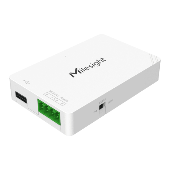
Page 5: Hardware Overview
www.ime.de 2.2 Hardware Overview 120Ω Terminal Resistor Switch: the device will add a 120Ω termination resistor to avoid data-corrupting reflections if RS485 data rate is high or cable length is long. 2.3 LED Patterns and Reset Button The reset button is inside the device. Device Status LED Status System is functioning properly... -
Page 6: Operation Guide
4. Operation Guide 4.1 Log in the ToolBox 1. Download ToolBox software from Milesight IoT website. 2. Power on the UC100 device, then connect it to computer via the type-C port. 3. Open the ToolBox and select type as General, then click password to log in ToolBox. (Default... -
Page 7: Lorawan Settings
www.ime.de 4. After logging in the ToolBox, you can change device settings. 4.2 LoRaWAN Settings LoRaWAN settings are used for configuring the transmission parameters in LoRaWAN ® network. Basic LoRaWAN Settings: Go to LoRaWAN Settings > Basic to configure join type, App EUI, App Key and other information. You can also keep all settings by default. - Page 8 www.ime.de Parameters Description Device EUI Unique ID of the device on the label. App EUI Default App EUI is 24E124C0002A0001. Application Port The port is used for sending and receiving data, the default port is 85. Working Mode Fixed as Class C. Join Type OTAA and ABP modes are available.
- Page 9 1) Please contact sales for device EUI list if there are many units. 2) Please contact sales if you need random App keys before purchasing. 3) Select OTAA mode if you use Milesight IoT Cloud to manage devices. 4) Only OTAA mode supports rejoin mode.
-
Page 10: General Settings
www.ime.de 1-40: Enabling Channel 1 to Channel 40 1-40, 60: Enabling Channel 1 to Channel 40 and Channel 60 All: Enabling all channels Null: Indicates that all channels are disabled 4.3 General Settings 4.3.1 Basic Settings Parameters Description Device ID Show the SN of the device. - Page 11 www.ime.de 2. Go to General > RS485 to enable RS485 and configure serial port settings. Serial port settings should be the same as the RS485 terminal devices. Parameters Description Stop Bit 1 bit/2 bit are available. Data Bit 8 bit is available. Parity None, Odd and Oven are available.
- Page 12 www.ime.de Select pass-through mode when Modbus RS485 bridge LoRaWAN is enabled. Active Pass-through: network server can send any type of command to RS485 device and RS485 device can only react according to server commands. Pass-through Two-way Pass-through: not only can network server send any type of Mode command to RS485 device, but also RS485 device supports transmitting the data to the network server actively.
-
Page 13: If-Then Command
www.ime.de 4.4 IF-THEN Command UC100 supports configuring locally IF-THEN commands to do some actions automatically even without a network connection. One device can be added 16 commands at most. 1. Go to Command page, and click Edit to add commands. 2. -
Page 14: Milesight D2D Settings
Send a Modbus This only works with Milesight D2D feature enabled. See details on chapter command via the 4.5. RS485 interface 4.5 Milesight D2D Settings Milesight D2D protocol is developed by Milesight and used for setting up transmission among... - Page 15 Milesight devices without a gateway. When the Milesight D2D setting is enabled, UC100 can work as a Milesight D2D controller to send control commands to other devices or work as a Milesight D2D agent to receive commands to trigger a reboot or message to the network server.
-
Page 16: Maintenance
When UC100 receives a Milesight D2D command, it can work as a Milesight D2D agent to reboot the device or send Modbus command to RS485 terminal devices. 4.6 Maintenance 4.6.1 Upgrade... -
Page 17: Backup
UC100 supports upgrade firmware locally via ToolBox software. 1. Download firmware from www.milesight-iot.com to your PC. 2. Go to Maintenance > Upgrade, click Browse to import firmware and upgrade the device. You can also click Up to Date to search for the latest firmware of the device and upgrade. -
Page 18: Reset To Factory Default
1 Byte M Bytes 1 Byte Among them, Data field are shown as little endian. For decoder examples, you can find them at https://github.com/Milesight-IoT/SensorDecoders. 5.1 Device Information UC100 reports basic device information of device every time joining the network. Channel... -
Page 19: Modbus Channel Data
www.ime.de Example: ff0bff ff0101 ff166445b43411300001 ff090100 ff0a0101 Channel Type Value 0b (Power Event) ff (powered on) 01 (Protocol Version) 01 (V1) 16 (Device SN) 64 45 B4 34 11 30 00 01 09 (Hardware Version) 0100 (V1.0) 0a (Software Version) 0101 (V1.1) 5.2 Modbus Channel Data UC100 reports RS485 sensor data which are fetched by Modbus channels according to reporting... - Page 20 www.ime.de Channel ID Description RS485 (Modbus Master) Channel 1 RS485 (Modbus Master) Channel 2 RS485 (Modbus Master) Channel 3 RS485 (Modbus Master) Channel 16 Examples: ff 19 07 02 03 15 00 Channel Type Channel ID Data Size Data Type Value 07 =>...
-
Page 21: Downlink Command
www.ime.de ff 15 00 Channel Type Value 15 (Poll Failed) 00 => Channel 1 5.3 Downlink Command UC100 supports downlink commands to configure the device. The application port is 85 by default. Channel Type Description 03(Set Reporting Interval) 2 Bytes, unit: s 10 (Reboot) ff (Reserved) Examples:...
Need help?
Do you have a question about the UC100-868M and is the answer not in the manual?
Questions and answers