Table of Contents
Advertisement
Advertisement
Table of Contents

Related Manuals for Starrett AV350


Summary of Contents for Starrett AV350
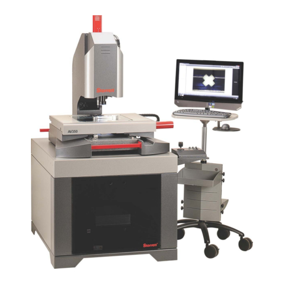
- Page 1 AV300, AV350, AV450 CNC Vision Metrology Systems with MetLogix M3 Software User Manual P/N 6659, Rev. August 1, 2016 Starrett Kinemetric Engineering 26052 Merit Circle, Suite 103 Laguna Hills, CA 92653, USA www.starrettkinemetric.com Phone: (949) 348-1213, Fax: (949) 582-804...
-
Page 2: Table Of Contents
Regulatory Compliance ....................... 5 Disclaimer of Liabilities ........................ 5 Copyright & Trademark Information .................... 5 2. PRODUCT INTRODUCTION ......................... 6 AV300, AV350, AV450 System Components ................9 Component Description ......................11 Manual Controls via Pendant..................... 13 Emergency Stop (E-Stop) Switches ..................13 Environmental Considerations .................... - Page 3 6.4.3 Cleaning Mechanical Parts....................34 Lubrication ..........................34 Auxiliary Lens Replacement ...................... 34 Bulb Replacement (Fiber-optic Lighting) ................... 35 Periodic Calibration and Maintenance Service ................36 Recommended Spare Parts ...................... 36 7. GLOSSARY ............................37 - 3 -...
-
Page 4: Preface
Thank you for purchasing an AV300, AV350 or AV450 Automatic Vision (CNC) metrology system with MetLogix M3 software. We are pleased that your search has led you to Starrett Kinemetric Engineering, a subsidiary of the L.S. Starrett Company. This manual is intended to maximize your satisfaction with your system and ensure the most in operating performance. -
Page 5: Regulatory Compliance
Safety of Laser Products Disclaimer of Liabilities The L.S. Starrett Company shall have no liability or responsibility to the customer or any other person or entity with respect to any liability, loss or damage caused or alleged to be caused directly or indirectly by this documentation, or the hardware described in it. -
Page 6: Product Introduction
AV300 systems feature a 513 x 275 mm (20.2” x 10.8”) stage, 300 x 150 x 135 mm (12” x 6” x 5.5”) of CNC XYZ travel. These systems are available as a benchtop system or with an ergonomic workstation that supports the system’s metrology unit, 24”... - Page 7 Calibration To NIST traceable calibration standards. Optional Items Quad ring light, auxiliary lenses (0.5X, 1.5X, 2X), parts fixturing, NIST traceable calibration standards, workstation for AV300 system. Quad Ring Light Option Lighting Elements 96 white LEDs in 4 individually controllable quadrants.
- Page 8 Touch Probe Option Kit Probe Head Renishaw PH6 Probe Body 1 Renishaw TP20 SF (standard force) Probe Body 2 Renishaw TP20 MF (medium force) Stylus Renishaw 20 mm long stylus with 2 mm ruby tip. Probe Tip Repeatability 0.35 μm Error Due to Z Travel <...
-
Page 9: Av300, Av350, Av450 System Components
CNC X-Y stage trackball unit for manual control Aluminum base Wireless mouse Wireless keyboard Workstation with extension on right side (optional) AV300 CNC System Components on Optional Workstation MetLogix M3 CNC Control Unit (installed in workstation) - 9 -... - Page 10 Ring light CNC Z-column for surface illumination CNC optical probe 24” touch-screen Sub-stage light monitor and PC Touch probe for silhouette (optional) illumination CNC X-Y stage Wireless keyboard Wireless mouse Joystick and trackball unit for manual control Control cart Machine pedestal (standard).
-
Page 11: Component Description
Surface mounting holes allow customer-designed fixtures for part support. Travel is 300 x 150 mm (12” x 6”) for AV300, 350 x 350 mm (14” x 14”) for AV350, and 450 x 350 mm (18” x 14”) for AV450. - Page 12 Emergency Stop (E-Stop) button. 12) Ergonomic Workstation. Available as an option with AV300 systems. Supports the AV300 metro- logy unit. Houses M3 controller, M3 control unit, power supplies, and quartz-halogen lamp housings (non-LED systems).
-
Page 13: Manual Controls Via Pendant
Press again to reapply power. Button in = energized Button out = de-energized 2.3 Environmental Considerations Starrett Vision Metrology Systems are factory calibrated under the standard laboratory environ- mental conditions shown below: Specification Requirement 68°F ± 1°F (20°C ± 0.5°C) -
Page 14: Changing Bayonet Mounted Optics
If the system is to be operated under environmental conditions that are substantially different from those shown above, the system should be recalibrated under the expected conditions. Also consider material characteristics, such as coefficients of thermal expansion of the parts under inspection. -
Page 15: Safety Considerations
Disconnect all power sources prior to moving or working on the equipment. Consult Starrett if you have any question regarding transporting, using or maintaining these systems. -
Page 16: System On/Off Controls
System On/Off Controls In AV350 and AV450 systems, the front panel of the pedestal has a master power switch for the system and a second power switch for the M3 controller. Use this second switch to reset and initialize the M3 controller when needed. Turning on the master power switch will automatically turn on the computer. -
Page 17: Stage Plate Diagrams
Stage Plate Diagrams The Stage Plate allows attachment of customer-designed fixtures for part support. Please refer to the following diagrams for bolt-hole placement and size. AV300 Stage Plate Diagram - 17 -... - Page 18 AV350 Stage Plate Diagram - 18 -...
- Page 19 AV450 Stage Plate Diagram - 19 -...
-
Page 20: Installation
Moving the Equipment Starrett AV Series vision metrology systems are shipped in a large wooden shipping crate. Use a forklift or pallet cart to move the crate within the building to the final location where the system will be installed. - Page 21 AV300 metrology unit outline dimensions AV350 and AV450 metrology unit outline dimensions - 21 -...
-
Page 22: Electrical Power
Electrical Power Brick-type power adapters AV300 systems are powered by three “brick” type AC adapters: one for the all-in-one touch- screen PC, one for the M3 controller, and one for the illumination controller. The AC adapters all accept 100/240 Vac power for worldwide use. They are normally plugged in a switchable outlet strip, which is shipped with the system and serves as the master power distribution point. -
Page 23: Installation
INSTALLATION Your metrology system was carefully secured in a custom crate for stability and protection during shipment. Exercise care in handling the shipping crate, as excessive force or shock may damage its delicate contents. Required Tools The following items are typically required to uncrate and install the metrology system: Phillips screwdriver Battery powered drill (Phillips bit recommended) Standard slotted screwdriver... -
Page 24: Lifting Of Av350 / Av450 Metrology Unit
Removing Shipping Retainers AV systems (and other Starrett metrology systems) use metal lock-down tabs to prevent move- ment of critical motion components during shipment. These are intended to be removed once the equipment has been placed in its final position. Look for the lock-down metal tabs and permanently remove them. - Page 25 Brick power supply Zoom drive current Zoom optics USB interface, PC to M3 controller "Amp box" X-Y-Z encoder signals M3 controller AV300 or AV350 X-Y-Z limit signals metrology unit X-Y-Z motor drive Joystick unit LED drive currents controller Surface, silhouette, on-axis...
- Page 26 Stage travel Stage travel Z motor X-Y-Z motor limit interface limit adapter controllers brake relay cables Image latch Power cable input AC adapter to Touch-probe X-Y-Z encoder Zoom control M3 controller Joystick connector cables cable cable Q encoder AC adapter to USB cable connector LED controller...
-
Page 27: Operation
1. Verify that all system components are in the Off position. 2. To apply power to the system PC and M3 controller in AV300 systems, turn on the AC power strip. With an AV350 or AV450 system, rotate the master power switch to the right to the On position (marked by “I”... -
Page 28: Cnc And Manual Control Modes
CNC and Manual Control Modes CNC programmable settings include X-Y stage position, Z-height (for focus adjustment), zoom, and lighting. M3 CNC metrology software is factory configured for AV300 and AV350 systems. Please refer to the separate M3 CNC Software manual. -
Page 29: Focus Considerations
5.4.4 Parts Fixturing The part must be fixtured securely to prevent part movement during measurement. Options are available from Starrett Kinemetric for off-the-shelf, semi-custom or custom fixturing. Please contact Starrett Kinemetric sales with your requirements. Aligning the part’s X or Y axis to the stage will improve dimensional measurements. If the part is off-axis from the stage, X-Y-Z measurements will not correlate as well with true part dimensions. -
Page 30: System Maintenance
Therefore, in order to properly inspect parfocality, always reference a flat, sharp edge. Do not select a rough or sloping feature. Starrett’s MAG checker is provided with the system and is an ideal part to use in parfocality inspection. -
Page 31: Parcentricity
5. While observing the feature, slowly adjust the magnification lower. Verify that the feature remains focused as the magnification is lowered. 6. Report any observed discrepancy. If the error is verified, contact your Starrett representative for authorized service. 6.2.2 Parcentricity Parcentricity describes the condition wherein a feature will remain at the optical center of the video image throughout the magnification range. -
Page 32: Calibration Verification
A calibration verification standard artifact is available from Starrett authorized distributors or directly from the Starrett service department. Calibration should also be verified after the system has been serviced or moved. The following is a brief description of the steps recommended for the verification of your machine. -
Page 33: Cleaning
Calibration Error Chart Example Cleaning To the degree possible, the system should be kept in a clean environment, away from dirt, dust, oil and debris which could affect system performance or degrade the system’s mechanical and electronic parts. If a clean environment is not available, the machine should be kept as clean and protected as is possible. -
Page 34: Cleaning Mechanical Parts
To ensure a long, trouble-free service life, wipe down the system regularly to remove any dust or dirt from the system. Most critical components are covered and require no user service. Should the stage or column mechanics require service, please contact your Starrett representative. Lubrication Every 6 months, lead-screws may be lubricated with a small amount of Tri-Flow®. -
Page 35: Bulb Replacement (Fiber-Optic Lighting)
Bulb Replacement (Fiber-optic Lighting) NOTE: The lights of a fiber-optic metrology system generate heat. To preserve lamp life and reduce unnecessary heat buildup, turn the lights down when the system is not in use. WARNING: Power the system down properly and unplug the unit from the power supply before opening the electronics enclosure. -
Page 36: Periodic Calibration And Maintenance Service
10. Replace the cover and properly tighten the retaining screws. 11. Plug the unit in and power the system on to check proper bulb function. 12. If further assistance is required, please contact your Starrett dealer or the factory. Eject Bulb... -
Page 37: Glossary
GLOSSARY The following terms may have additional meanings. The definitions that follow are in context of the Starrett Vision Metrology Systems. Accuracy The maximum error that the system will produce when measuring a true standard. Auxiliary Lens An accessory lens that may be attached to zoom optics to increase magnification or increase the field of view. - Page 38 100 mm (or 4”) lower. In AV300 and AV350 systems, the height adjustment is motorized using the system’s Z-Track lead screw feature.
- Page 39 Object Telecentric lens CCD detector Tetrafluoroethylene, a self-lubricating polymer coating used on precision lead screws. Video Edge Detection, a system where a video camera and digital image processing are used to detect edges and other features. Zoom Optics Optics which can change magnification based on a user selection. Zoom control can be manual or motorized, depending on the metrology system.
Need help?
Do you have a question about the AV350 and is the answer not in the manual?
Questions and answers