Table of Contents
Advertisement
Quick Links
Advertisement
Table of Contents

Related Manuals for Sleipner PJC212


Summary of Contents for Sleipner PJC212
- Page 1 User Manual Including Installation For Control Panels PJC211 & PJC212 DOCUMENT ID: SLEIPNER AS 2917 REVISION: P.O. Box 519 DATE: N-1612 Fredrikstad 2020 Norway LANGUAGE: www.sleipnergroup.com To download your language go to www.sleipnergroup.com...
-
Page 2: Table Of Contents
Product Spare Parts and Additional Resources ..........................30 Warranty Statement .................................... 30 Patents......................................... 30 Products PJC212 - Prop.ctrl. panel 12/24V DC + AC PJC211 - Prop.ctrl. panel 12/24V DC + AC Sleipner Motor AS P.O. Box 519, Arne Svendsensgt. 6-8 N-1612 Fredrikstad, Norway MC_0020 PJC 211 &... -
Page 3: Responsibility Of The User Operating Thrusters
Failure to follow the considerations and precautions can cause serious injury, damage and will render all warranties given by Sleipner Motor as VOID. MC_0411 Responsibility of the User Operating Thrusters MC_0418 Never use thrusters when close to objects, persons or animals in the water. The thruster will draw objects into the tunnel and the rotating propellers. -
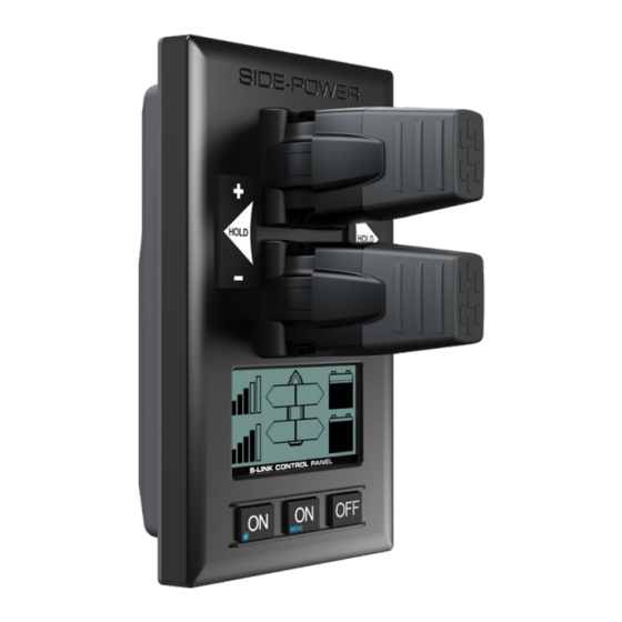
Page 4: Panel Layout & Functions
Panel Layout & Functions MC_0116 PJC-211 Speed control joystick for thruster Holding function for auto-running 1of bow and stern thrusters together in the direction of the arrows at Information display, selected power see following pages Press “+” for more and “-” for details. -
Page 5: Proportional Control Panel
Proportional Control Panel Activating the stern thruster Activating the bow thruster *Bow thruster installation only *Stern thruster installation only *Control panel example *Control panel example Activating both bow and stern thruster Activating both bow and stern thruster to push the boat sideways to rotate the boat on axis *Bow and stern *Bow and stern... -
Page 6: Setup Procedure
Setup Procedure MC_0094 At the fi rst start-up of a new system, one of the two screens below will be shown: SETUP DO NOT MATCH SYSTEM. PRESS FOR AUTO SETUP New devices found. Not in conflict with other devices. Press button below the -symbol to auto setup. -
Page 7: Control Panel Setup Buttons
(NB: If the boat has Sleipner stabilizer and AC or DC thrusters the thruster location should be set as BOW-STB or STERN-STB. This so the hydraulic controller are shown at the left side in display and thruster(s) at the right side of the display.) -
Page 8: Ac System - Pdc 301 Setup
BOW-STB or STERN-STB for starboard thruster. (NB: If the boat has Sleipner stabilizer and AC or DC thrusters the thruster location should be set as BOW-STB or STERN-STB. This so the hydraulic controller are shown at the left side in display and thruster(s) at the right side of the display.) -
Page 9: Dc System - Automatic Main Switch Setup
STERN-STB for starboard thruster. (NB: If the boat has Sleipner stabilizer and AC or DC thrusters the thruster location should be set as BOW-STB or STERN-STB. This so the hydraulic controller are shown at the left side in display and thruster(s) at the right side of the display.) -
Page 10: Dc System - Rcrs 1 & Rcrs 2 Setup
DC System - PPC, SR150000, SR61242 Setup MC_0097 Extended runtime Values: OFF (default), ON (this is only for PPC520/820/840 from V1.030) OFF: Extended runtime function is off. ON: This will increase the thrusters maximum runtime but at the same time reduce the maximum thrust when the motor temperature is high. -
Page 11: Hold Calibration
Calibrates the HOLD-function to get balanced thrust from the bow and stern thruster. If only one thruster or PJC221/PJC211 you will not get any balanced thrust, but you can adjust the maximum thrust from HOLD buttons. Hold-button represents 1/6 of the calibrated value. -
Page 12: Information - Pdc101 & Pdc201
Information - PDC101 & PDC201 MC_0098 PDC101 and PDC 201 (Controller for AC electric thrusters) Motor Speed: RPM on motor output shaft Motor Power: Motor power consumption in % (PDC201 only) Motor Temp: Temperature measured in motor Thrust: Thrust level from joystick/hold buttons Information - PDC301 MC_0098 PDC-301 (SAC controller) -
Page 13: Menu System - Panel Setup
Menu System - Panel Setup MC_0101 • Move between parameters with the (stern) joystick. • Press the button below to return to the previous menu. • Press the button below to edit the selected parameter. • Parameter value will start to blink, use joystick to alter value. •... -
Page 14: Alarm System
front s_v strek_PJC222.pdf 1 04.11.2010 11:05:34 Alarm System MC_0101 When there is an alarm or a fault, the panel will show this alarm situation by changing LCD display back light to red colour. The panel will also change to show “Alarm Info” on the bottom of the screen, indicating that by pressing the corresponding button below, you will get information about what the problem is (examples below). -
Page 15: Proportional Thruster Display
Proportional Thruster Display MC_0053 PJC221 PJC222 PJC211 PJC212 Status indicators for bow BOW-STB Status indicators for starboard thruster. (Port bow thruster bow thruster. Only shown in in a dual bow thruster setup). a dual bow thruster setup. Runtime indicator will be shown here... -
Page 16: Proportional Thruster Display Symbols
Proportional Thruster Display Symbols MC_0053 DC Thrusters: Motor temperature indicator. Battery indicator. From 70°C/ 158°F to 130°C/266°F. From 8.5V to 12V for 12V thrusters, 15V to 24V for 24V thrusters Symbol shown when a DC Thruster is used in a dual bow or dual stern setup: Battery indicator. -
Page 17: Hold Function
HOLD Function MC_0053 The ‘HOLD’ function is for auto-run ning of bow and stern thrusters together in the direction of the arrows at selected power. Press “+” for more and “-” for less power (6 steps). The ‘HOLD’ function is normally used to hold the boat into the dock while mooring. The ‘HOLD’ function can be deactivated by running any thruster in the opposite direction from any control unit. -
Page 18: Menu System
MENU System MC_0053 LANGUAGE • Choose language by moving joystick: English, Norwegian, German, French, Spanish, Italian and Danish. LANGUAGE • Press the button below to set the language to the highlighted menu entry. A star (*) on each side indicates the language set. -
Page 19: Alarm Descriptions
Alarm Descriptions MC_0053 "Ext. buzzer "Err. "Auto Errors shown in display activation at Description Action No." Reset" Alert Level" ² Motor current too high. "Thruster must be serviced by Motor Overcurrent authorized personnel, reset or power OFF/ON PPC ¹ ." ²... - Page 20 Alarm Descriptions MC_0053 "Ext. buzzer "Err. "Auto Errors shown in display activation at Description Action No." Reset" Alert Level" Actuator Fault ² Actuator not getting any power "Check actuator connection or power to actuator. Reset alarm in alarm menu on PJC 211/212/221/222 or recycle power."...
-
Page 21: Phc-3 Alarm Descriptions
PHC-3 Fault Codes MC_0117 Fault Code Description Cause Action "-Limit use of thruster 10500.0.10 PHC Oil Level - Level Low Hydraulic oil level is low -Inspect hydraulic oil level -Check system for leaks and refi ll hydraulic oil" "-Sensor not connected or wire break. -Verify sensor type in parameter 0201 10500.0.13 PHC Oil Level - Open Circuit... -
Page 22: Pdc-301 Alarm Descriptions
PHC-3 Fault Codes MC_0117 Fault Code Description Cause Action 10515.0.51 PHC DOUT 6 - Current High Digital Output 6 current higher than 4.0A -Check wires and connections for short circuit Digital Output 3 is confi gured as crossover and output is open "-Check for open circuit, power consumption <... -
Page 23: Responsibility Of The Installer
Sleipner products. If you are interfacing the S-Link™ bus by agreement with Sleipner through a designated Sleipner supplied interface, you are still required to install at least one original Sleipner control panel to enable efficient troubleshooting if necessary. -
Page 24: Control Panel Installation
Control Panel Installation MC_0042 ! Please refer to the graphic for special considerations relating to your model ! Find a suitable location for the control panel where it does not obstruct or is obstructed by other devices. Install the control panel on a flat surface where it is easy to use. -
Page 25: Measurements
Measurements MC_0359 *PJC211 *PJC212 Measurement Measurement description code inch inch Panel Height 5.55 5.55 Panel width Raised height above the dashboard 65.66 65.66 Depth behind the dashboard (not inc. cables) 31.8 1.25 31.8 1.25 Panel screw hole diameter 0.18 0.18 Distance between panel screw holes 132.7... -
Page 26: Technical Specifications & Measurements
Technical Specifi cations and Measurements MC_0104 Description Minimum Maximum Units Comment Input voltage Volt DC Powered from S-Link Current Voltage External Alarm Buzzer Voltage Volt DC External Alarm Buzzer Current Internally fused Description Value Operating temperature -10 to + 60 degrees C. Storage temperature -20 to + 70 degrees C. -
Page 27: S-Link Description
MC_0120 S-Link is a CAN-based control system used for communication between Sleipner products installed on a vessel. The system uses BACKBONE Cables as a common power and communication bus with separate SPUR Cables to each connected unit. Units with low power consumption are powered directly from the S-Link bus therefore one power cable must be connected to the BACKBONE Cable through a T-Connector. -
Page 28: Control Panel Cable Installation
(NB: If two or more control panels are operated at the same time in opposite directions, the electronic control box will stop the thruster until it receives a single signal or thrust in one direction.) • Sleipner on/off equipment it is entirely “plug & play” and require no additional confi guration setup. See the Control panel manual for more information. PJC 212... -
Page 29: Note Type, Location And Serial Numbers
List of Installed S-Link Devices MC_0102 Fill in the type, location and serial numbers of the S-link devices installed. Keeping this as a reference will make the setup procedure easier! S-link device Location Serial number (ie Thruster, AMS, PPC etc) (Bow, Bow-STB, Stern, Stern-STB) PJC 211 &... -
Page 30: Service And Support
10. This warranty gives you specific legal rights, and you may also have other rights which vary from country to country. Patents MC_0024 At Sleipner we continually reinvest to develop and offer the latest technology in marine advancements. To see the many unique designs we have patented visit our website www.sleipnergroup.com/patents PJC 211 & 212... - Page 31 Notes MC_0037 ..............................................................................................................................................................................................................................................................................................................................................................................................................................................................................................................................................................................................................................................................................................................................................................................................................................................................................................................................................................................................................................................................................................................................................................................................................................................................................................................................................................................................................................................................................................................................................................................................................PJC 211 & 212 2917 2020...
- Page 32 © Copyright Sleipner Motor AS, 2021 The information given in the document was correct at the time it was published. However, Sleipner Motor AS can not accept liability for any inaccuracies or omissions it may contain. Continuous product improvement may change the product specifi...
Need help?
Do you have a question about the PJC212 and is the answer not in the manual?
Questions and answers