Table of Contents
Advertisement
Quick Links
Advertisement
Table of Contents

Related Manuals for Sleipner PJC221


Summary of Contents for Sleipner PJC221
- Page 1 User Manual Including Installation For Control Panels PJC221 & PJC222 DOCUMENT ID: SLEIPNER GROUP 3059 REVISION: P.O. Box 519 DATE: N-1612 Fredrikstad 2024 Norway LANGUAGE: www.sleipnergroup.com To download your language go to www.sleipnergroup.com...
-
Page 2: Table Of Contents
Alarm Descriptions ....................................24 PHC-3 Fault Codes ....................................26 PDC-301 Fault Codes ..................................29 eVision and EHP Fault Codes ................................29 SRC-3 Fault Codes ....................................30 Sleipner Motor AS P.O. Box 519, Arne Svendsensgt. 6-8 N-1612 Fredrikstad, Norway MC_0020 PJC 221 & 222... -
Page 3: General Operation Consideration And Precaution Guidelines
Product Spare Parts and Additional Resources ..........................38 Warranty Statement .................................... 38 Patents......................................... 38 Failure to follow the considerations and precautions can cause serious injury, damage and will render all warranties given by Sleipner Motor as VOID. MC_0411 General Operation Consideration and Precaution Guidelines MC_0444... -
Page 4: Panel Layout & Functions
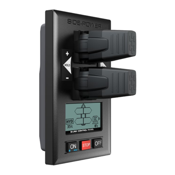
Panel Layout & Functions MC_0103 PJC-221 Speed control joystick for thruster Holding function for auto-running of bow and stern thrusters together in the direction of the arrows at selected power Press “+” for more and “-” for less power (6 steps). Information display, see following pages for details. -
Page 5: Proportional Control Panel
Proportional Control Panel Activating the stern thruster Activating the bow thruster *Bow thruster installation only *Stern thruster installation only *Control panel example *Control panel example Activating both bow and stern thruster Activating both bow and stern thruster to push the boat sideways to rotate the boat on axis *Bow and stern *Bow and stern... -
Page 6: Setup Procedure
Setup Procedure MC_0094 At the fi rst start-up of a new system, one of the two screens below will be shown: SETUP DO NOT MATCH SYSTEM. PRESS FOR AUTO SETUP New devices found. Not in conflict with other devices. Press button below the -symbol to auto setup. -
Page 7: Control Panel Setup Buttons
SETUP NOTICE regarding following Location modes: If the boat has Sleipner stabilizer and AC or DC thrusters the thruster location should be set as BOW-STB or STERN-STB. This so the hydraulic controller are shown at the left side in display and thruster(s) at the right side of the display. - Page 8 Hydraulic System - PHC024 Setup MC_0095 Cooling Power Save (only available for PHC024 with FW V1.101 or higher) Values: ON/OFF (default) ON sets the Cooling Pump into power save mode, which means the Cooling Pump output is dropping to 0 volt when the oil pressure is below 10 bar for more than 10 seconds (Cooling Pump is turned OFF).
-
Page 9: Hydraulic System - Phc-3 Setup
Hydraulic System - PHC-3 Setup MC_0095 PHC-3 - Controller for hydraulic thrusters PHC-3 has several parameters that can be changed for different setup requirements. These parameters can also be confi gured directly on the PHC-3 controller’s display. Firmware version and S-Link serial number are displayed at the bottom of the confi guration menu. Bow/Stern Direction: Values: Normal (default)/Inverted Switches between Normal and Inverted running direction for the thruster. -
Page 10: Ac System - Pdc 101 Setup
(NB: If the boat has Sleipner stabilizer and AC or DC thrusters the thruster location should be set as BOW-STB or STERN-STB. This so the hydraulic controller are shown at the left side in display and thruster(s) at the right side of the display.) -
Page 11: Ac System - Pdc-301 Setup
BOW or STERN for port thruster, BOW-STB or STERN-STB for starboard thruster. If the boat has Sleipner hydraulic stabilizer and AC thrusters the thruster location should be set as BOW-STB or STERN-STB. Then the hydraulic controller is shown at the left side in the display and thruster(s) at the right side of the display. -
Page 12: Dc System - Automatic Main Switch Setup
(i.e a catamaran), use BOW or STERN for port thruster, BOW-STB or STERN-STB for starboard thruster. (NB: If the boat has Sleipner hydraulic stabilizer and DC thrusters the thruster location should be set as BOW-STB or STERN-STB. This so the hydraulic controller are shown at the left side in display and thruster(s) at the right side of the display.) -
Page 13: Dc System - Evision Setup
BOW or STERN for port thruster, BOW-STB or STERN-STB for starboard thruster. If the vessel has Sleipner hydrulic stabilizer installed and DC thrusters the thruster location should be set as BOW-STB or STERN-STB. This ensures that the hydraulic controller is shown at the left side in the display and thruster(s) at the right side of the display. -
Page 14: Retract System - Sr150000 Setup
SR150000 - Control unit for retract thrusters 11.0 The Sleipner Retract Controller SR150000 is used to control and monitor deployment of retractable thrusters. Several parameters can be confi gured for SR150000. Firmware version and S-Link serial number are displayed at the bottom of the confi guration menu. -
Page 15: Retract System - Sr6 1242 Setup
12.0 SR6 1242 - Control unit for retract thrusters The Sleipner Retract Controller SR6 1242 is used to control and monitor deployment of retractable thrusters. Several parameters can be confi gured for SR6 1242. Firmware version and S-Link serial number are displayed at the bottom of the confi guration menu. -
Page 16: Hold Calibration
Calibrates the HOLD-function to get balanced thrust from the bow and stern thruster. If only one thruster or PJC221/PJC211 you will not get any balanced thrust, but you can adjust the maximum thrust from HOLD buttons. Hold-button represents 1/6 of the calibrated value. -
Page 17: Information - Pdc 101 & Pdc 201
Information - PDC 101 & PDC 201 MC_0098 PDC 101 and PDC 201 (Controller for AC electric thrusters) Motor Speed: RPM on motor output shaft Motor Power: Motor power consumption in % (PDC 201 only) Motor Temp: Temperature measured in motor Thrust: Thrust level from joystick/hold buttons Information - PDC-301... -
Page 18: Menu System - Panel Setup
Menu System - Panel Setup MC_0101 • Move between parameters with the (stern) joystick. • Press the button below to return to the previous menu. • Press the button below to edit the selected parameter. • Parameter value will start to blink, use joystick to alter value. •... -
Page 19: Alarm System
(examples below). Entering “Alarm Info” menu will silence the alarm on all PJC221 and PJC222 panels. Alarm code Some alarms needs an reset to stop alerting. -
Page 20: Proportional Thruster Display
Proportional Thruster Display MC_0053 PJC221 PJC222 PJC211 PJC212 Status indicators for bow BOW-STB Status indicators for starboard thruster. (Port bow thruster bow thruster. Only shown in in a dual bow thruster setup). a dual bow thruster setup. Runtime indicator will be shown here... -
Page 21: Proportional Thruster Display Symbols
Proportional Thruster Display Symbols MC_0053 DC Thrusters: Motor temperature indicator. Battery indicator. From 70°C/ 158°F to 130°C/266°F. From 8.5V to 12V for 12V thrusters, 15V to 24V for 24V thrusters Symbol shown when a DC Thruster is used in a dual bow or dual stern setup: Battery indicator. -
Page 22: Hold Function
HOLD Function MC_0053 The ‘HOLD’ function is for auto-run ning of bow and stern thrusters together in the direction of the arrows at selected power. Press “+” for more and “-” for less power (6 steps). The ‘HOLD’ function is normally used to hold the boat into the dock while mooring. The ‘HOLD’ function can be deactivated by running any thruster in the opposite direction from any control unit. -
Page 23: Menu System
MENU System MC_0053 LANGUAGE • Choose language by moving joystick: English, Norwegian, German, French, Spanish, Italian and Danish. LANGUAGE • Press the button below to set the language to the highlighted menu entry. A star (*) on each side indicates the language set. -
Page 24: S-Link Fault Codes
Please see the user manual of your S-Link compliant control panel for more information on how to access Fault Code information in case of an alarm situation. All Sleipner S-Link compliant products have product specifi c Fault Codes. For legacy reasons some control panels display Generic Fault Codes for certain products. - Page 25 Alarm Descriptions MC_0053 "Ext. buzzer "Err. "Auto Errors shown in display activation at Description Action No." Reset" Alert Level" Actuator Fault ² Actuator not getting any power "Check actuator connection or power to actuator. Reset alarm in alarm menu on PJC 211/212/221/222 or recycle power."...
-
Page 26: Phc-3 Fault Codes
PHC-3 Fault Codes MC_0117 Fault Code Fault Name Fault Description Action 106.202.0 Emergency Stop Bow - Bow emergency stop is button activated -Release bow emergency stop 106.203.0 Emergency Stop Bow Starboard - Bow Starboard emergency stop is button activated -Release bow starboard emergency stop 106.204.0 Emergency Stop Bow Port - Bow Port emergency stop is button activated... - Page 27 PHC-3 Fault Codes MC_0117 Fault Code Fault Name Fault Description Action -Wires shorted or sensor defective, check wiring/sensor 10505.0.16 PHC AI 2 - Short Circuit Analog Input 2 (4-20mA) sensor short circuit -Replace sensor -Check for open circuit, power consumption < 5.0 Watt 10508.0.13 PHC DOUT AC PUMP UNLOAD - Open Circuit AC Pump Unload valve open circuit...
- Page 28 PHC-3 Fault Codes MC_0117 Fault Code Fault Name Fault Description Action -Check if ECI pump is connected -Check wires to ECI pump for open circuits 10524.0.100 PHC ECI Cooling Pump - No Communication No communication with ECI cooling pump -Check power supply cooling pump -Wrong cooling pump confi...
-
Page 29: Pdc-301 Fault Codes
Internal error -Consult Side-Power dealer -Check S-link cables and T-connectors. 107.0.24 Bootloader fault code - Fault Bootloader failed upgrading. -If problem persist, consult Sleipner dealer. 155.0.24 Internal Voltage - Fault Internal error -If problem persist, consult Sleipner dealer. 10000.106.55 Motor Temp eVision Controller uC Overtemp... -
Page 30: Src-3 Fault Codes
Action 100.0.0 System Error - - System Error Contact Sleipner Dealer Verify that the correct battery was chosen for this system and that 153.0.151 Supply Voltage - Self-Test Fault Failed to determine voltage level of the system / Out of range. -
Page 31: Responsibility Of The Installer
Any attempt to directly control or connect into the S-Link™ control system without a designated and approved interface will render all warranties and responsibilities of all of the connected Sleipner products. If you are interfacing the S-Link™ bus by agreement with Sleipner through a designated Sleipner supplied interface, you are still required to install at least one original Sleipner control panel to enable efficient troubleshooting if necessary. -
Page 32: Product Measurements
5.22 Distance between panel screw holes 75.7 75.7 Panel cut out height Panel cut out width 2.64 2.64 Models: PJC211 PJC212 PJC221 PJC222 *Cut out *Stern Joystick Control Panel (PJC212) (PJC222) *Cut out MG_0399 PJC 221 & 222 3059 2024... -
Page 33: Product Specifications
Product Specifi cations MC_0104 Description Minimum Maximum Units Comment Input voltage Volt DC Powered from S-Link Current Voltage External Alarm Buzzer Voltage Volt DC External Alarm Buzzer Current Internally fused Description Value Operating temperature -10 to + 60 degrees C. Storage temperature -20 to + 70 degrees C. -
Page 34: Control Panel Installation
Control Panel Installation MC_0042 ! Please refer to the graphic for special considerations relating to your model ! Find a suitable location for the control panel where it does not obstruct or is obstructed by other devices. Install the control panel on a flat surface where it is easy to use. -
Page 35: S-Link System Description
MC_0120 S-Link is a CAN-based control system used for communication between Sleipner products installed on a vessel. The system uses BACKBONE Cables as a common power and communication bus with separate SPUR Cables to each connected unit. Only one S-Link POWER cable shall be connected to the BACKBONE Cable. -
Page 36: Control Panel Cable Installation
(NB: If two or more control panels are operated at the same time in opposite directions, the electronic control box will stop the thruster until it receives a single signal or thrust in one direction.) • Sleipner on/off equipment it is entirely “plug & play” and require no additional confi guration setup. See the Control panel manual for more information. PJC 212... -
Page 37: List Of Installed S-Link Devices
List of Installed S-Link Devices MC_0102 Fill in the type, location and serial numbers of the S-link devices installed. Keeping this as a reference will make the setup procedure easier! S-link device Location Serial number (ie Thruster, AMS, PPC etc) (Bow, Bow-STB, Stern, Stern-STB) PJC 221 &... -
Page 38: Service And Support
11. This warranty gives you specific legal rights, and you may also have other rights which vary from country to country. Patents MC_0024 At Sleipner we continually reinvest to develop and offer the latest technology in marine advancements. To see the many unique designs we have patented visit our website www.sleipnergroup.com/patents PJC 221 & 222... - Page 39 Notes MC_0037 ..............................................................................................................................................................................................................................................................................................................................................................................................................................................................................................................................................................................................................................................................................................................................................................................................................................................................................................................................................................................................................................................................................................................................................................................................................................................................................................................................................................................................................................................................................................................................................................................................................PJC 221 & 222 3059 2024...
- Page 40 © Sleipner Group, All rights reserved The information given in the document was right at the time it was published. However, Sleipner Group cannot accept liability for any inaccuracies or omissions it may contain. Continuous product improvement may change the product specifi...
Need help?
Do you have a question about the PJC221 and is the answer not in the manual?
Questions and answers