Table of Contents
Advertisement
Advertisement
Table of Contents

Related Manuals for TBB power DDX1230


Summarization of Contents
General Safety Instruction
1.1 Safety Instruction
Safety precautions for qualified personnel and manual reading before installation.
1.2 General Precaution
Advice on wiring, cable quality, and proper unit placement to avoid hazards.
1.3 Precaution regarding battery operation
Handling battery acid and flammable gases, and removing metal objects during operation.
Description of main functions
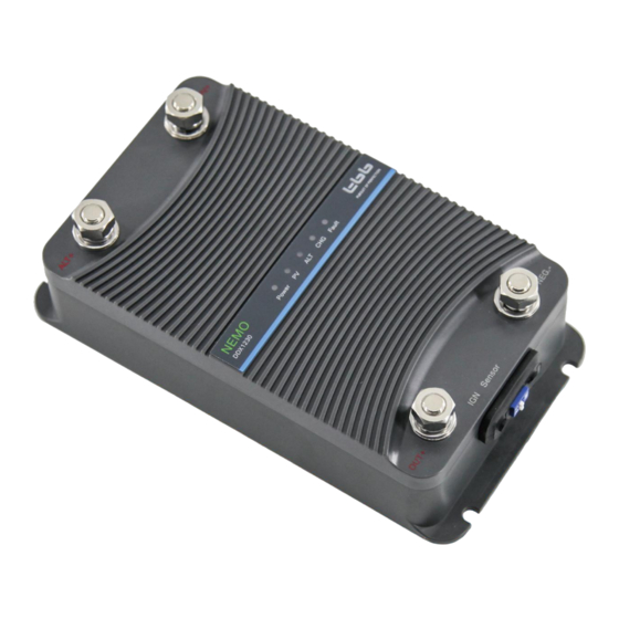
2.1 General Description
Overview of the NEMO charger's capabilities, features, and vehicle compatibility.
2.2 Principle Diagram
Functional block diagram illustrating charger components and their interconnections.
2.3 Model Information
Details on model naming conventions and a breakdown of different series.
Structure
3.1 Terminal and panel definition
Identification and description of the charger's terminals, connectors, and panel layout.
3.2 Structure dimension
Physical dimensions and overall structural layout of the charger unit.
Preparation and Configuration
4.1 Material list
List of supplied materials and accessories included with the charger.
4.2 Location
Guidelines for selecting an optimal and safe installation location for the charger.
4.3 Battery type setting
Instructions for setting the charger to match specific battery types using dip switches.
4.4 Wiring and Fuse recommendation
Recommended cable sizes, fuse ratings, and wiring practices for safe installation.
Installation and Connection
5.1 General advice
General recommendations for a safe and effective installation process.
5.2 Connecting the power cable
Step-by-step instructions for correctly connecting the power input and output cables.
Operation
6.1 Double check
Essential pre-operation checks to ensure correct setup and readiness.
6.2 LED Description
Explanation of LED indicators for various operational states and model differences.
6.3 LEDs indicate the normal working status
Interpretation of LED patterns indicating normal working conditions for different models.
Need help?
Do you have a question about the DDX1230 and is the answer not in the manual?
Questions and answers