
Related Manuals for TBB power BP Series


Summary of Contents for TBB power BP Series
- Page 1 BP Smart Battery Charger User Manual V1.1 BP Series SMART BATTERY CHARGER USER MANUAL Version 1.1 Date: May, 2014 TBB Power Co. Ltd.
-
Page 2: Table Of Contents
BP Smart Battery Charger User Manual V1.1 Contents 1.General Safety Information............................1 2.INTRODUCTION...............................2 2.1 Description................................2 2.2 BP Series Features............................2 2.3Indicator Lights and Settings on the Front Panel....................5 3.INSTALLING GUIDE..............................7 3.1 Material List..............................7 3.2 Preparing for Installation..........................7 3.3 Installing BP Series............................8 3.4 Installing Battery Temperature Sensor......................9 4.OPERATION................................11... -
Page 3: About This Manual
Please consult the battery manufacturer for this information. Audience The manual is for anyone intending to install and operate a TBB BP Series battery charger. Warning This charger is not designed for any life retaining equipment. -
Page 4: Contact Information
We ensure consistent product quality by subjecting every product to strictly choice of superior quality components, rigorous testing and burn-in through out the production process. TBB Power is certified by TUV in accordance with ISO9001 and can be your reliable power solution provider. -
Page 5: General Safety Information
Use BP Series battery charger only for its use as intended. Use BP Series battery charger only in well ventilated rooms. Do not expose the charger to rain, snow, spray, or bilge water. To reduce risk of fire hazard, do not cover or obstruct the ventilation openings. -
Page 6: Introduction
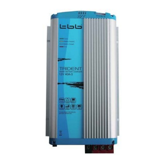
BP Smart Battery Charger User Manual V1.1 INTRODUCTION 2.1 Description 2.1.1 Front Panel 2.1.2 Rear Panel TBB Power Co. Ltd. -
Page 7: Bp Series Features
2.2.3 Dip Switches BP Series battery charger has dip switches for you to choose: charge mode, battery type and to support R/C or R/D. Please refer to 4.1 for detail setting. -
Page 8: Isolated Design
2.2.8 Parallel design for recharging and power supply. BP Series smart battery charger can be used to supply your DC load and charge your battery simultaneously. Specially designed software is being programmed to avoid overcharging your battery at this circumstance. - Page 9 2.2.9 Power Supply Choice Easy to choose, the BP Series can work as a power supply by dip switch. It is meant that the output of the battery charger is a fixed voltage. It is not meant for charging batteries. The battery type and battery temperature are ignored in this mode.
- Page 10 PCB. 2.2.14 Optional remote controller or remote display available. Easy to switch the signal between remote controller and remote displayer by dip switch. Please read the chapter 7 for the details setting and content. TBB Power Co. Ltd.
-
Page 11: Indicator Lights And Settings On The Front Panel
Batteries charging(constant voltage stage) "Charged" Batteries charged (Floating) Polarity inversion on output "Reverse Polarity" Charger over tem, charger will reduce the FLASHING output power "Charging" and "Charged" FLASHING Will reduce the output power, then shut off. TBB Power Co. Ltd. -
Page 12: Installing Guide
Cool: For best performance, the ambient air temperature should be between 32F (0 ℃) and 95F (30 ℃), the cooler the better. At higher ambient temperature, BP Series battery charger can work, but the output current will be automatically reduced to protect the charger from high internal temperatures. -
Page 13: Installing Bp Series
12A — 4mm2 minimum (AWG 11) 20A/25A — 8mm2 minimum (AWG 8) 40A — 13mm2 minimum (AWG 6) 3.3 Installing BP Series WARNING Shock and Energy Hazards Be sure to read the safety guidelines and pay attention to all cautions and warnings throughout the installation procedure. - Page 14 Leave the DC disconnects or breakers in the OFF position until installation is complete. Leaving them off helps prevent sparking when you actually make the connection. Connect AC Wiring TBB Power Co. Ltd.
-
Page 15: Installing Battery Temperature Sensor
AC input cable to a properly grounded ground terminal in the AC distribution panel. 3.4 Installing Battery Temperature Sensor Strongly recommend to install the temperature sensor which is offered together with the battery charger for a pro- per charging of your batteries. TBB Power Co. Ltd. -
Page 16: Operation
4.2 Charging Batteries Before you start to charge batteries, please read the "General safety information" and take all safety precautions when working with batteries. Read the section 4.1 to set the dip switch at proper situation. TBB Power Co. Ltd. -
Page 17: Simultaneously Recharging And Power Supply
Many generators provide output voltage that is modified sine wave (MSW) rather than the true sine wave (TSW) that your utility provides. TBB does not permit the use of BP Series + with modified sine wave generator due to increased heating of the charger. -
Page 18: Technical Specification
24VDC for 24V models 12V12A 12ADC; 12V25A 25ADC; 12V40A 40ADC; Rated DC output current (total) 24VI2A 12ADC; 24V20A 20ADC Automatic 6 steps charging curves. Soft start, bulk, Charge Algorithms compensation, absorption, floating, recycle. Nominal input voltage 185-265VAC 50Hz, TBB Power Co. Ltd. -
Page 19: Protection Features
50℃ 30VDC(24V models) Battery over voltage limits Will not continue charging if any battery voltage is greater than 16.0VDC (12V models) and 32VDC(24V models) 5.4 Approvals EN60335-1, EN60335-2-29 EN55014-1/EN55014-2,EN61000-3-2/EN61000-3-3 TBB Power Co. Ltd. -
Page 20: Maintenance And Troubleshooting
TROUBLESHOOTIN 6.1 Maintenance WARNING Risk of Electrical Shock BP Series battery charger contains no user serviceable components. Do not attempt servicing unless you are a qualified technician or electrician. Contact your dealer or the manufacturer for service information. Cleaning: BP Series battery charger contains solid-state electronic components that require no maintenance. - Page 21 "Reverse polarity" indicator light ON Polarity reversion on output Charger over temp. charger will reduce the “Reverse polarity" indicator light flashing output power "Charging" & "Charged" indicator light flashing Will reduce the output power, then shut off. TBB Power Co. Ltd.
-
Page 22: Remote Controller
BP Smart Battery Charger User Manual V1.1 REMOTE CONTROLLER Remote controller and remote display are available for BP Series battery charger. You can buy them from the local distributor separately. 7.1 Brief Introduction For your convenience, remote controller of BP Series smart battery charger offers plenty of information and powerful function. - Page 23 CHARGED Shows the charged REVERSE Reverse polarity TIME time since the battery POLARITY error. 00000H00M charger is power on Shows the charged CHARGED amps hour since the 000000 AH battery charger is power TBB Power Co. Ltd.
-
Page 24: Installation Guide
Put the dip switch on correct position on the battery charger: Switch 5 Switch 6 Switch 7 Switch 8 Please use screw (M4) to fix the remote controller onto dashboard, please refer to pic B. PIC A: PIC B: TBB Power Co. Ltd. - Page 25 BP Smart Battery Charger User Manual V1.1 TBB Power Co. Ltd.
-
Page 26: Remote Display
Connect cable to remote display and battery charger. Put the dip switch on correct position on the battery charger: Switch 5 Switch 6 Switch 7 Switch 8 Please use screw (M4) to fix the remote display onto dashboard, please refer to Pic D. TBB Power Co. Ltd. - Page 27 BP Smart Battery Charger User Manual V1.1 PIC C: PIC D: TBB Power Co. Ltd.
Need help?
Do you have a question about the BP Series and is the answer not in the manual?
Questions and answers