Table of Contents
Advertisement
Quick Links
For use in Hazardous Locations Class I, Division 2 or equivalent Class I, Zone 2
© Panduit Corp. 2018
The VeriSafe Absence of Voltage Tester is a permanently-mounted tester that is used to verify a circuit is de-
energized prior to opening an electrical enclosure. Once installed, a push of a button enables qualified electrical
workers to verify the absence of voltage and see an active indication when the absence of voltage is confirmed.
The Indicator Module is designed for a 30-mm notched panel knockout and the Isolation Module can be mounted
to DIN rail or surface mounted using screws.
TO REDUCE THE RISK OF INJURY, USER
MUST READ INSTRUCTION MANUAL
Email:
techsupport@panduit.com
EU Website:
www.panduit.com/emea
EU Email:
emeatoolservicecenter
@panduit.com
VeriSafe AVT
Absence of Voltage Tester
Instruction Manual
Models: VS-AVT2-C02L03, VS-AVT2-C08L10
NOTE: In the interest of higher quality and value, Panduit products are
continually being improved and updated. Consequently, pictures may vary from
the enclosed product.
NOTE: Updates to this Instruction Manual may be available. Check
www.panduit.com for the latest version of this manual.
www.panduit.com
Technical Support:
Tel: 1-866-405-6654
Panduit Europe • EMEA Service Center
Almelo, Netherlands
Tel: +31-546-580-452 • Fax: +31-546-580-441
B21075
Rev: 00 04-2018
Original Instructions
Advertisement
Chapters
Table of Contents

Related Manuals for Panduit VS-AVT2-C08L10


Summarization of Contents
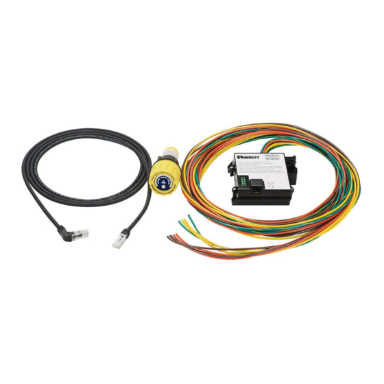
VeriSafe AVT Components
VeriSafe Indicator Module Faceplate Color
Shows different indicator module faceplate colors and model numbers for VeriSafe AVT.
AVT System Cable
Connects the Indicator Module to the Isolation Module.
Indicator Module
The main indicator unit of the VeriSafe AVT system.
Isolation Module
Houses the primary sensing and safety circuitry for the AVT.
Sensor Lead Wires
Wires that connect to the circuit for voltage detection.
Output Contact Specifications
Details the electrical ratings and capabilities of the AVT's output contacts.
Technical Specifications Overview
Standards Compliance
Lists relevant industry standards and certifications for the VeriSafe AVT.
Application Suitability
Information on where the AVT can be used, including hazardous locations.
Environmental Specifications
Operating temperature, storage, humidity, pollution, and altitude limits.
Battery Specifications
Details the type and voltage of the battery used in the AVT.
Functional Safety Parameters
Includes failure rate, integrity levels, and demand response time.
Dimensions and Panel Knockout
Isolation Module Dimensions
Provides detailed measurements for the Isolation Module.
Indicator Module Dimensions
Provides detailed measurements for the Indicator Module.
Panel Knockout Dimensions
Specifies the required size and shape for panel mounting holes.
Wiring Schematics
Three-Phase Delta Wiring Schematic
Shows the wiring diagram for a 3-wire + PE Delta system.
Three-Phase WYE Wiring Schematic
Shows the wiring diagram for a 3-wire + Neutral + PE WYE system.
Three-Phase WYE (No Neutral) Wiring Schematic
Wiring diagram for a 3-wire + PE WYE system without a neutral connection.
Three-Phase WYE High Resistance Ground Wiring Schematic
Wiring diagram for a high resistance grounded WYE system.
Single-Phase 2 Wire + PE Wiring Schematic
Wiring diagram for a 2-wire + PE single-phase system.
Single-Phase 2 Wire Redundant Wiring Schematic
Wiring diagram for a single-phase system with redundant detection.
Single-Phase 3 Wire + PE Wiring Schematic
Wiring diagram for a 3-wire + PE single-phase system.
Corner Grounded Delta Wiring Schematic
Wiring diagram for a corner-grounded Delta system.
High-Leg Delta Wiring Schematic
Wiring diagram for a high-leg Delta system with neutral and ground.
DC System 2 Wire + PE Wiring Schematic
Wiring diagram for a 2-wire + PE DC system.
DC System 2 Wire Redundant Wiring Schematic
Wiring diagram for a DC system with redundant detection.
Installation Considerations
General Installation Information
Key points to consider before installing the VeriSafe AVT.
SCCR Considerations
Impact of the AVT on the Short Circuit Current Rating of the equipment.
Overcurrent Protection Use
Guidelines for using overcurrent protection with the AVT.
Termination Considerations
Proper methods for terminating sensor leads and ground connections.
Connectivity Test Procedure
Performing the Connectivity Test
Steps and warnings for verifying AVT connectivity and sensor lead function.
Installation Instructions
Indicator and Isolation Module Installation
Step-by-step guide for installing the Indicator and Isolation Modules.
Cable and Label Installation
Instructions for connecting AVT cables, terminating leads, and applying labels.
Commissioning Checklist
Commissioning and Verification Checklist
A comprehensive checklist to ensure proper installation and initial operation.
Operating Instructions
Understanding Indicators and Controls
Explains the function of voltage indicators, absence indicators, and the test button.
Performing the Absence of Voltage Test
Detailed steps for performing the absence of voltage test.
Troubleshooting
Common Issues and Resolutions
Identifies common AVT symptoms (flashes) and their corresponding solutions.
Maintenance Procedures
Battery Replacement Procedure
Step-by-step instructions for safely replacing the AVT battery.
AVT System Cable Removal
Procedure for disconnecting and removing the AVT system cable.
O-ring Replacement
Recommendations for replacing O-rings to ensure proper sealing.
Cleaning Instructions
Guidelines for cleaning the AVT Indicator Module and other parts.
Visual Inspection Guidelines
What to look for during visual checks of the AVT components.
Warranty Information
Panduit Limited Product Warranty
Details the terms and conditions of the product warranty.
Need help?
Do you have a question about the VS-AVT2-C08L10 and is the answer not in the manual?
Questions and answers