Table of Contents
Advertisement
Models: VS-AVT-C02-L10, VS-AVT-C02-L03, VS-AVT-C08-L10, VS-AVT-C02-L03A, VS-AVT-C08-L10A
© Panduit Corp. 2018
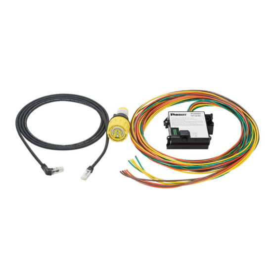
The VeriSafe Absence of Voltage Tester is a permanently-mounted tester that is used to verify a circuit is
de-energized prior to opening an electrical enclosure. Once installed, a push of a button enables qualified
electrical workers to verify the absence of voltage and see an active indication when the absence of voltage is
confirmed. The Indicator Module is designed for a 30-mm notched panel knockout and the Isolation Module can
be mounted to DIN rail or surface mounted using screws.
TO REDUCE THE RISK OF INJURY, USER
MUST READ INSTRUCTION MANUAL
North America Tech Support:
techsupport@panduit.com
Tel: 1-866-405-6654
EU Tech Support :
emeatoolservicecenter
@panduit.com
Tel: +31-546-580-452
Fax: +31-546-580-441
VeriSafe AVT
Absence of Voltage Tester
Instruction Manual
NOTE: In the interest of higher quality and value, Panduit products are
continually being improved and updated. Consequently, pictures may vary
from the enclosed product.
NOTE: Updates to this Instruction Manual may be available. Check
www.panduit.com for the latest version of this manual.
www.panduit.com
Original Instructions
Asia Pacific Tech Support:
TechSupportAP@ panduit.com
Telephone:
Singapore: 1-800-Panduit (7263848)
Australia: 1-800-Panduit (7263848)
Korea: 02-21827300
B21052
Rev: 05 4-2018
Advertisement
Table of Contents

Related Manuals for Panduit VeriSafe AVT VS-AVT-C02-L10


Summary of Contents for Panduit VeriSafe AVT VS-AVT-C02-L10
- Page 1 DIN rail or surface mounted using screws. TO REDUCE THE RISK OF INJURY, USER MUST READ INSTRUCTION MANUAL NOTE: In the interest of higher quality and value, Panduit products are continually being improved and updated. Consequently, pictures may vary from the enclosed product.
-
Page 2: Table Of Contents
INSTRUCTION MANUAL VeriSafe AVT © Panduit Corp. 2018 Table of Contents Safety Information ..........................2 Information de Sécurité ........................3 Components ............................ 4 Output Contacts ..........................4 Technical Specifications ........................5 Dimensions ............................7 Schematics ............................8 Installation Considerations ......................11 Installation Instructions........................13... -
Page 3: Safety Information
Should a problem occur during installation, operation or maintenance of the VeriSafe AVT, contact Panduit using one of the technical support or customer service numbers listed on the cover of this manual. Contact Panduit if you have any product problems related to the safety function of the product. -
Page 4: Information De Sécurité
éviter tout mouvement où cas si la terminaison ne reste pas intacte. En cas de problème lors de l'installation, du fonctionnement ou de la maintenance de VeriSafe AVT, contactez Panduit en utilisant l'un des supports techniques ou les numéros de service clientèle figurant sur le couvercle de ce manuel. Veuillez contacter Panduit si vous avez des problèmes de produits liés à... -
Page 5: Components
© Panduit Corp. 2018 Components The components of the Panduit VeriSafe Absence of Voltage Tester (AVT) Output Contacts The AVT includes a set of redundant dry contact signal outputs for optional use with control systems. These contacts are located on the Isolation Module. -
Page 6: Technical Specifications
INSTRUCTION MANUAL VeriSafe AVT © Panduit Corp. 2018 Technical Specifications Warning: Do not use this product outside of the specified performance and environmental limits. Failure to comply with these specifications could result in product failure, personal injury, or death. Standards... - Page 7 INSTRUCTION MANUAL VeriSafe AVT © Panduit Corp. 2018 Environment Operating Temperature 0°C to 60°C (32°F to 140°F) Storage Temperature -45°C to 85°C (-49°F to 185°F) Humidity 5 to 90% non-condensing; Rated 80% at 40°C, decreasing linearly to 50% at 60°C...
-
Page 8: Dimensions
INSTRUCTION MANUAL VeriSafe AVT © Panduit Corp. 2018 Dimensions Isolation Module MOUNTING HOLES (3) Units = inches [mm] Indicator Module Units = inches [mm] Panel Knockout The Indicator Module is designed for use with a standard 30 mm knockout with notch. -
Page 9: Schematics
INSTRUCTION MANUAL VeriSafe AVT © Panduit Corp. 2018 Schematics Warning The AVT must be installed correctly and grounded as described in this Instruction Manual to provide proper indication of • absence of voltage. Sensor leads must not be mechanically connected with each other for the device to verify connection to the circuit. - Page 10 INSTRUCTION MANUAL VeriSafe AVT © Panduit Corp. 2018 Single-Phase: 2 Wire + PE Single-Phase: 2 Wire + PE, Redundant Detection Lead Single-Phase: 3 Wire + PE Corner Grounded DELTA: 3 Wire + PE High-Leg DELTA: 3 Wire + Neutral + PE...
- Page 11 INSTRUCTION MANUAL VeriSafe AVT © Panduit Corp. 2018 DC System: 2 Wire + PE, Redundant Detection Lead B21052_05 Page: 10 of 20 4-2018...
-
Page 12: Installation Considerations
INSTRUCTION MANUAL VeriSafe AVT © Panduit Corp. 2018 Installation Considerations This section provides guidelines for installing VeriSafe Absence of Voltage Testers (AVTs). It also addresses several common application scenarios and describes best practices. General Information Before installing the AVT, identify all sources of electrical energy in the equipment. Install the AVT at the point in the circuit where you would normally test for voltage. - Page 13 INSTRUCTION MANUAL VeriSafe AVT © Panduit Corp. 2018 Connectivity Test Each time the absence of voltage test is initiated, the VeriSafe AVT performs a series of diagnostics and checks in addition to testing for absence of voltage. One step in this sequence involves a “connectivity test.” The purpose of the connectivity test is to ensure that each detection lead is in contact with a conductor.
-
Page 14: Installation Instructions
INSTRUCTION MANUAL VeriSafe AVT © Panduit Corp. 2018 Installation Instructions Warning: The AVT must be installed correctly and grounded as described in this Instruction Manual to provide proper indication • of absence of voltage. Sensor leads must not be mechanically connected with each other for the device to verify connection to the circuit. - Page 15 INSTRUCTION MANUAL VeriSafe AVT © Panduit Corp. 2018 Insert the other end of the AVT 7. Terminate the sensor and ground leads. Route Sensor Leads and AVT System System Cable in the connector Secure the sensor leads to the conductors and...
-
Page 16: Commissioning Checklist
INSTRUCTION MANUAL VeriSafe AVT © Panduit Corp. 2018 Commissioning Checklist: □ Visually inspect the AVT: o AVT system cable: Verify cable is locked into place on both the Indicator Module and Isolation Module. o Indicator module: Ensure o-ring is in place. Check that retaining nut is secure. Verify battery is installed and battery cap is locked into place. -
Page 17: Operating Instructions
INSTRUCTION MANUAL VeriSafe AVT © Panduit Corp. 2018 Operating Instructions Warning: • To avoid electric shock, always de-energize power before entering an electrical enclosure. • Always follow safety and lockout/tagout procedures when working on or near electrical systems and equipment. -
Page 18: Troubleshooting
Should a problem occur during installation, operation or maintenance of the VeriSafe AVT, contact Panduit using one of the technical support or customer service numbers listed on the cover of this manual. Contact Panduit if you have any product problems related to the safety function of the product. The product model number and serial number are printed on the Isolation Module and Indicator Module labels. -
Page 19: Maintenance
INSTRUCTION MANUAL VeriSafe AVT © Panduit Corp. 2018 Maintenance Warning: The product uses a lithium battery that is a fire, explosion and severe burn hazard. Do not crush, recharge, • ° disassemble or heat above 85 C, incinerate, or expose contents to water. -
Page 20: Avt System Cable Removal
INSTRUCTION MANUAL VeriSafe AVT © Panduit Corp. 2018 AVT System Cable Removal 1. Grip the Retention Spring on both Continue holding the Retention Spring sides. down while pulling back on the right-angle connector to release the AVT System Cable. 2. Pull down on the Retention Spring approximately 1/16 inch [1.5 mm]. -
Page 21: Warranty
Panduit product, and each part or component of the Panduit product, will comply with Panduit’s published specifications and will be free from defects in material and workmanship for a period of 1 year from the date of invoice from Panduit or its authorized distributor, not to exceed 18 months from the original date of shipment from Panduit’s facility.
Need help?
Do you have a question about the VeriSafe AVT VS-AVT-C02-L10 and is the answer not in the manual?
Questions and answers