Table of Contents
Advertisement
OPERATING AND MAINTENANCE MANUAL
Section 1
a)
Operating and Maintenance Text
Section 2
a)
General Arrangement Drawing ................................................................................... 74119
b)
Wiring Diagram 208-240 /1/ 50/60 .............................................................................. 50339
c)
Wiring Diagram 208-240 /3/ 50/60 .............................................................................. 50340
d)
Wiring Diagram 380-415 /3/ 50/60 .............................................................................. 50341
e)
Wiring Diagram 460 /3/ 50/60 ..................................................................................... 50342
f)
Wiring Diagram 208-240 /3/ 50/60 .............................................................................. 50344
Section 3
a)
Replacing Fusible Links
b)
Humidistat Field Connections ..................................................................................... 26992
c)
Blastgate Installation Instructions ............................................................................... 27110
d)
Recommended Spare Parts List ................................................................................ 21239
MODEL: HC-300 / DEW-300
Advertisement
Table of Contents

Related Manuals for Munters DEW-300


Summarization of Contents
1 - INTRODUCTION
1.1 DEHUMIDIFIER OPERATING PRINCIPLE
Explains the mechanism by which the HC-300 removes moisture from the air using a desiccant wheel.
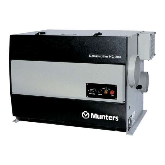
1.2 ABOUT THE HC-300
Provides an overview of the HC-300 unit's components and function.
1.3 CONTROLS AND INDICATORS
Details the unit's control panel, including switches, indicators, and time meter.
1.4 PROTECTIVE CIRCUITS
Describes sensors and circuits that protect the machine and operator from potential hazards.
3 - INSTALLATION AND START-UP
3.1 INSPECTION
Instructions for checking the unit for shipping damage and verifying components upon arrival.
3.2 POSITIONING THE UNIT
Provides dimensions and required clearances for properly positioning the HC-300 unit.
3.3 CONNECTING THE DUCTWORK
Details on connecting ductwork for process and reactivation air streams for optimal performance.
3.4 ELECTRICAL CONNECTIONS
Instructions and safety warnings for making electrical connections to the HC-300 unit.
3.5 CONNECTING THE REMOTE HUMIDISTAT
Guidance on wiring and installing a remote humidistat for automatic unit control.
3.6 ADJUSTING THE DAMPERS
Steps for adjusting process and reactivation dampers to optimize unit performance and temperature.
4 - PREVENTIVE MAINTENANCE
4.1 CLEAN THE AIR FILTERS
Procedure for cleaning or replacing the process and reactivation air filters.
4.2 CHECK THE HONEYCOMBE® WHEEL
Instructions for inspecting the HoneyCombe wheel for correct rotation and signs of wear.
4.3 CHECK THE UPPER AND LOWER AIR SEALS
Guidance on checking the air seals for wear and condition.
4.4 CHECK THE REACTIVATION OUTLET TEMPERATURE
How to measure and verify the reactivation air outlet temperature.
5 - TROUBLESHOOTING
5.1 POSSIBLE TROUBLE CONDITIONS
General advice on preparing the unit for troubleshooting and identifying potential issues.
5.2 AUTO/OFF/MANUAL SWITCH IS SET TO AUTO, RUNNING LIGHT DOES NOT COME ON
Troubleshooting steps when the unit does not start in auto mode.
5.3 FAULT LIGHT IS ON, AND MACHINE SHOULD BE RUNNING
Diagnosing issues when the fault light is illuminated during operation.
5.4 REACTIVATION OUTLET TEMPERATURE IS TOO LOW
Steps to identify causes for a low reactivation outlet air temperature.
5.5 POOR DEHUMIDIFYING PERFORMANCE
Troubleshooting steps for reduced dehumidification capacity.
5.6 HONEYCOMBE® WHEEL IS STOPPED, RUNNING LIGHT IS ON
Diagnosing why the HoneyCombe wheel has stopped while the unit is running.
5.7 CHECKING THE HEATING ELEMENTS
Procedure for testing the unit's heating elements for proper function.
5.8 CHECKING THE THERMISTOR
Guidance on testing the thermistor that controls the heating elements.
5.9 CHECKING THE HUMIDISTAT
Steps to check the functionality and wiring of the humidistat.
5.10 CHECKING THE DRIVE MOTOR, WHEEL AND SEALS
Procedure for inspecting and servicing the drive motor, HoneyCombe wheel, and seals.
HC-150 and HC-300 Humidistat Field Connections
Viconics Humidistat Wiring
Wiring diagram for connecting a Viconics humidistat to the HC-300 input plug.
Regin Humidistat Wiring
Wiring diagram for connecting a Regin humidistat to the HC-300 input plug.
Direct Connect to HC-150/300 Circuit Board
Viconics Humidistat to PCB1 Connection
Diagram showing direct connection of a Viconics humidistat to the main unit's PCB1.
Rotronics Humidistat Connection
Wiring diagram for connecting a Rotronics SF-D65 humidistat.
BLASTGATE INSTALLATION INSTRUCTIONS
HC-300 Blastgate Installation
Procedure for installing blastgates onto the HC-300 process outlet connection ring.
Blastgate Ductwork Connection
Instructions for connecting blastgates to ductwork for process and reactivation outlets.
Need help?
Do you have a question about the DEW-300 and is the answer not in the manual?
Questions and answers