Table of Contents
Advertisement
OPERATING AND MAINTENANCE MANUAL
Section 1
a)
Operating and Maintenance Text
Section 2
a)
General Arrangement Drawing ................................................................................... 74119
b)
Wiring Diagram 208-240 /1/ 50/60 .............................................................................. 50339
c)
Wiring Diagram 208-240 /3/ 50/60 .............................................................................. 50340
d)
Wiring Diagram 380-415 /3/ 50/60 .............................................................................. 50341
e)
Wiring Diagram 460 /3/ 50/60 ..................................................................................... 50342
f)
Wiring Diagram 208-240 /3/ 50/60 .............................................................................. 50344
Section 3
a)
Replacing Fusible Links
b)
Humidistat Field Connections ..................................................................................... 26992
c)
Blastgate Installation Instructions ............................................................................... 27110
d)
Recommended Spare Parts List ................................................................................ 21239
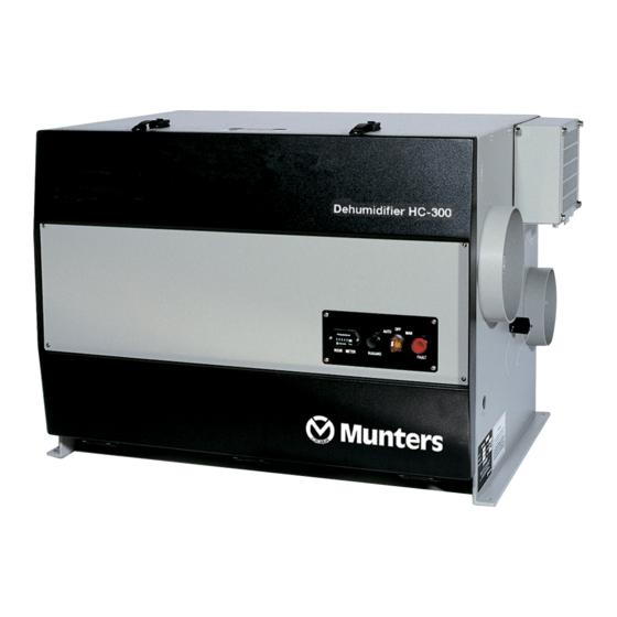
MODEL: HC-300 / DEW-300
Advertisement
Table of Contents


Need help?
Do you have a question about the HC-300 and is the answer not in the manual?
Questions and answers