Table of Contents
Advertisement
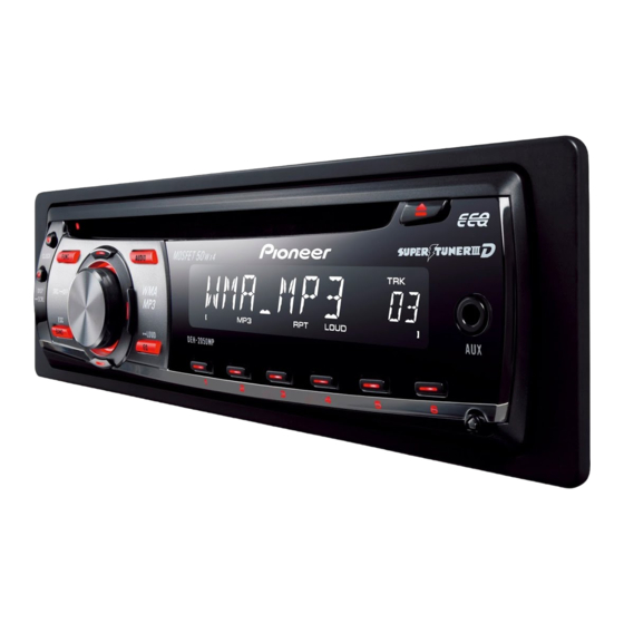
CD RECEIVER
DEH-2050MPA
DEH-2050MPG
DEH-2090MP
This service manual should be used together with the following manual(s):
Model No.
Order No.
CX-3195
CRT3815
For details, refer to "Important Check Points for Good Servicing".
PIONEER CORPORATION
PIONEER ELECTRONICS (USA) INC. P.O. Box 1760, Long Beach, CA 90801-1760, U.S.A.
PIONEER EUROPE NV Haven 1087, Keetberglaan 1, 9120 Melsele, Belgium
PIONEER ELECTRONICS ASIACENTRE PTE. LTD. 253 Alexandra Road, #04-01, Singapore 159936
PIONEER CORPORATION 2007
Mech.Module
S10.5COMP2
CD Mech. Module : Circuit Descriptions, Mech. Descriptions, Disassembly
4-1, Meguro 1-chome, Meguro-ku, Tokyo 153-8654, Japan
DEH-2050MPA/XN/EC
/XN/EC
/XN/ID
Remarks
ORDER NO.
CRT4045
/XN/EC
K-ZZU. OCT. 2007 Printed in Japan
Advertisement
Table of Contents

Related Manuals for Pioneer DEH-2090MP


Summarization of Contents
SAFETY INFORMATION
Service Precautions for those who Service this Unit
Safety advice for technicians performing repairs on the unit.
Important Check Points for Good Servicing
1. Product safety
Ensure compliance with product regulations and maintain a safe servicing environment.
2. Adjustments
Maintain optimum product performance by performing adjustments as per manual instructions.
3. Lubricants, Glues, and Replacement parts
Use specified lubricants, adhesives, and replacement parts as required for servicing.
4. Cleaning
Perform proper cleaning of critical parts to restore product performance.
5. Shipping mode and Shipping screws
Implement shipping mode or screws to protect products from damage during transit.
SERVICE PRECAUTIONS
1.1 SERVICE PRECAUTIONS
General safety guidelines and precautions to be followed during product servicing.
1.2 NOTES ON SOLDERING
Important notes and guidelines concerning the use of lead-free solder for repairs.
SPECIFICATIONS
2.1 SPECIFICATIONS
Detailed technical specifications for the product's various functions and performance.
2.2 DISC/CONTENT FORMAT
Information on supported disc types and content formats for playback.
PANEL FACILITIES
Head unit Controls
Descriptions of buttons and functions available on the main head unit.
Remote control
Explanation of the operations and functions controlled by the remote unit.
Connection Diagram
Wiring diagram illustrating how the product connects to other components and power.
BASIC ITEMS FOR SERVICE
3.1 CHECK POINTS AFTER SERVICING
Key points to verify after service to ensure product quality and proper function.
3.2 PCB LOCATIONS
Diagrams identifying the physical locations of Printed Circuit Boards within the unit.
3.3 JIGS LIST
A list of specialized jigs and tools required for servicing the product.
BLOCK DIAGRAM
4.1 BLOCK DIAGRAM
A graphical representation of the product's internal functional blocks and connections.
DIAGNOSIS
5.1 OPERATIONAL FLOW CHART
A flowchart illustrating the sequence of operations for diagnosing unit issues.
5.2 Error Code List
A comprehensive list of error codes displayed by the unit and their potential causes.
5.3 CONNECTOR FUNCTION DESCRIPTION
Detailed descriptions of the function of each pin for all unit connectors.
SERVICE MODE
6.1 CD TEST MODE
Procedure for entering and using the CD test mode for adjustments and diagnostics.
6.2 CHECKING THE GRATING AFTER CHANGING THE PICKUP UNIT
Procedure to check the grating angle after replacing the pickup unit.
DISASSEMBLY
Removing the Case
Step-by-step instructions for removing the external case of the unit.
Removing the CD Mechanism Module
Procedure for safely removing the CD mechanism module from the unit.
Removing the Grille Assy
Instructions for detaching and removing the front grille assembly.
Removing the Tuner Amp Unit
Steps to remove the tuner amplifier unit from the main chassis.
How to hold the Mechanism Unit
Guidelines on the correct method for holding and manipulating the mechanism unit.
Removing the Upper and Lower Frames
Procedure for disassembling the upper and lower frames of the mechanism.
How to remove the CD Core Unit
Detailed steps for removing the CD core unit assembly from the mechanism.
How to remove the Pickup Unit
Instructions for removing the pickup unit, including related components.
EACH SETTING AND ADJUSTMENT
8.1 PCL OUTPUT CONFIRMATION
Procedure to confirm the PCL output signal characteristics.
EXPLODED VIEWS AND PARTS LIST
9.1 PACKING
Exploded view and parts list detailing items included in the product packing.
PACKING SECTION PARTS LIST
A detailed list of all parts included in the product packing, with part numbers.
9.2 EXTERIOR
Exploded view illustrating the external components and their assembly.
EXTERIOR SECTION PARTS LIST
A detailed list of external parts, including part numbers and descriptions.
9.3 CD MECHANISM MODULE
Exploded view showing the components of the CD mechanism module.
CD MECHANISM MODULE SECTION PARTS LIST
Detailed list of parts for the CD mechanism module, with part numbers.
SCHEMATIC DIAGRAM
10.1 OVERALL CONNECTION DIAGRAM(GUIDE PAGE)
Comprehensive schematic diagram showing overall unit connections and signal flow.
10.2 KEYBOARD UNIT
Schematic diagram detailing the connections and components of the keyboard unit.
10.3 CD MECHANISM MODULE(GUIDE PAGE)
Schematic diagram illustrating the connections and components of the CD mechanism module.
C CD CORE UNIT(S10.5COMP2)
Schematic diagram for the CD core unit, showing its internal circuitry.
10.4 WAVEFORMS
Illustrations of key signal waveforms used for troubleshooting and adjustment.
PCB CONNECTION DIAGRAM
11.1 TUNER AMP UNIT
PCB connection diagram for the tuner amplifier unit.
11.2 KEYBOARD UNIT
PCB connection diagram for the keyboard unit.
11.3 CD CORE UNIT(S10.5COMP2)
PCB connection diagram for the CD core unit.
ELECTRICAL PARTS LIST
Chip Resistor
List of chip resistor components with their part numbers.
Chip Capacitor
List of chip capacitor components with their part numbers.
MISCELLANEOUS
List of miscellaneous electrical parts and their corresponding part numbers.
RESISTORS
List of resistor components with their part numbers and circuit symbols.
CAPACITORS
List of capacitor components with their part numbers and circuit symbols.
Need help?
Do you have a question about the DEH-2090MP and is the answer not in the manual?
Questions and answers