Table of Contents
Advertisement
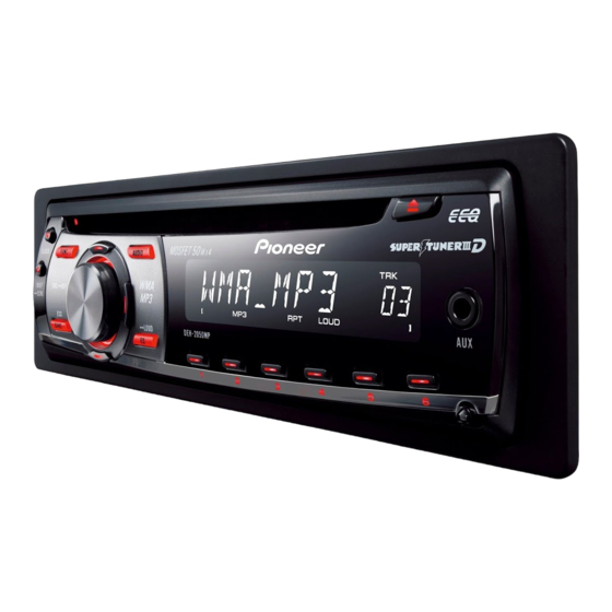
CD RECEIVER
DEH-2050MPA
DEH-2050MPG
DEH-2090MP
This service manual should be used together with the following manual(s):
Model No.
Order No.
CX-3195
CRT3815
For details, refer to "Important Check Points for Good Servicing".
PIONEER CORPORATION
PIONEER ELECTRONICS (USA) INC. P.O. Box 1760, Long Beach, CA 90801-1760, U.S.A.
PIONEER EUROPE NV Haven 1087, Keetberglaan 1, 9120 Melsele, Belgium
PIONEER ELECTRONICS ASIACENTRE PTE. LTD. 253 Alexandra Road, #04-01, Singapore 159936
PIONEER CORPORATION 2007
Mech.Module
S10.5COMP2
CD Mech. Module : Circuit Descriptions, Mech. Descriptions, Disassembly
4-1, Meguro 1-chome, Meguro-ku, Tokyo 153-8654, Japan
DEH-2050MPA/XN/EC
/XN/EC
/XN/ID
Remarks
ORDER NO.
CRT4045
/XN/EC
K-ZZU. OCT. 2007 Printed in Japan
Advertisement
Table of Contents

Related Manuals for Pioneer DEH-2050MPG


Summarization of Contents
SAFETY INFORMATION
Safety Precautions for those who Service this Unit
General safety advice for service technicians regarding product handling and repairs.
CAUTION
Warning regarding battery replacement and disposal, emphasizing correct procedures.
Important Check Points for Good Servicing
1. Product safety
Conforming to regulations, safe environment, using specified parts, proper soldering, and cord safety.
2. Adjustments
Maintaining product performance through optimum adjustments as per manual instructions.
3. Lubricants, Glues, and Replacement parts
Using specified lubricants and adhesives in the correct amount for repairs.
4. Cleaning
Proper cleaning of optical pickups, heads, and lenses to restore performance.
5. Shipping mode and Shipping screws
Setting shipping mode or screws to protect products from transit damage.
1. SERVICE PRECAUTIONS
1.1 SERVICE PRECAUTIONS
General precautions for servicing, including power off, ESD protection, and IC handling.
1.2 NOTES ON SOLDERING
Guidelines for using lead-free solder, soldering iron temperature, and available solder types.
2. SPECIFICATIONS
2.1 SPECIFICATIONS
Detailed technical specifications for General, AM tuner, Audio, CD player, and FM tuner.
2.2 DISC/CONTENT FORMAT
Information on supported disc types and content formats like CD-DA, WMA, and MP3.
2.3 PANEL FACILITIES
Head unit
Description and function of buttons and controls on the main unit.
Remote control
Explanation of remote control operations, matching head unit functions.
2.4 PANEL FACILITIES
Connection Diagram
Diagram showing external connections for power, speakers, antenna, and accessories.
3. BASIC ITEMS FOR SERVICE
3.1 CHECK POINTS AFTER SERVICING
Key checks to perform after service, including customer complaint resolution and appearance.
3.2 PCB LOCATIONS
CD Core Unit(S10.5)
Location of the CD Core Unit on the PCB layout.
Tuner Amp Unit
Location of the Tuner Amp Unit on the PCB layout.
Keyboard Unit
Location of the Keyboard Unit on the PCB layout.
3.3 JIGS LIST
Jigs List
List of jigs used for testing and servicing, including Test Disc and L.P.F.
Grease List
List of greases used for CD Mechanism Module maintenance.
4. BLOCK DIAGRAM
4.1 BLOCK DIAGRAM
Overall block diagram illustrating the system architecture and component interactions.
5. DIAGNOSIS
5.1 OPERATIONAL FLOW CHART
Flowchart illustrating the power-on sequence and system initialization process.
5.2 Error Message
Error Messages
List of error codes displayed by the unit, with descriptions and potential causes.
6. SERVICE MODE
6.1 CD TEST MODE
Procedure for entering and exiting CD test mode, including operational notes and cautions.
6.2 CHECKING THE GRATING AFTER CHANGING THE PICKUP UNIT
Note
Importance of PU unit compatibility and procedure for checking grating angle.
Purpose
To verify the grating angle is within acceptable limits after PU unit replacement.
Symptoms of Mal-adjustment
Signs of incorrect grating angle, affecting tracking and track search operations.
Method
Required measuring equipment, points, disc, and mode for checking grating.
Checking Procedure
Step-by-step instructions for checking the grating angle using test mode and oscilloscope.
Hint
Tip to reduce disc clamping position wobble by reloading the disc.
7. DISASSEMBLY
Removing the Case (not shown)
Instruction to remove the outer case of the unit.
Removing the CD Mechanism Module (Fig.1)
Steps to remove the CD mechanism module, including screw removal and connector disconnection.
Removing the Grille Assy (Fig.1)
Steps to detach the grille assembly, involving releasing latches.
Removing the Tuner Amp Unit (Fig.2)
Steps to remove the tuner amp unit, involving screws, tabs, and connectors.
8. EACH SETTING AND ADJUSTMENT
8.1 PCL OUTPUT CONFIRMATION
Procedure to confirm PCL output, including signal frequency checks and X'tal replacement.
9. EXPLODED VIEWS AND PARTS LIST
NOTES
Notes on parts availability, safety factors, disassembly screws, and lubricant application.
9.1 PACKING
Exploded view and parts list related to the product's packing and shipping components.
10. SCHEMATIC DIAGRAM
10.1 OVERALL CONNECTION DIAGRAM(GUIDE PAGE)
Overall connection diagram showing the interconnections between major units and components.
10.4 WAVEFORMS
CD Core Unit
Waveforms for CD core unit signals like DSCSNS, CLCONT, VD, LOEJ, and loading operations.
11. PCB CONNECTION DIAGRAM
11.1 TUNER AMP UNIT
PCB connection diagram for the Tuner Amp Unit, showing component placement and connector locations.
12. ELECTRICAL PARTS LIST
RESISTORS
Electrical parts list for resistors, including circuit symbol, part number, and PCB coordinates.
CAPACITORS
Electrical parts list for capacitors, including circuit symbol, part number, and PCB coordinates.
Need help?
Do you have a question about the DEH-2050MPG and is the answer not in the manual?
Questions and answers