Table of Contents
Advertisement
Service
Manual
HIGH POWER CD PLAYER WITH RDS TUNER
DEH-2000R
DEH-2030R
DEH-2020R
- See the separate manual CX-916(CRT2300) for the CD mechanism description, disassembly and circuit
description.
- The CD mechanism employed in this model is one of S8 series.
CONTENTS
1. SAFETY INFORMATION ............................................2
2. EXPLODED VIEWS AND PARTS LIST .......................3
3. SCHEMATIC DIAGRAM ...........................................14
4. PCB CONNECTION DIAGRAM ................................38
5. ELECTRICAL PARTS LIST ........................................48
6. ADJUSTMENT..........................................................56
PIONEER ELECTRONIC CORPORATION
PIONEER ELECTRONICS SERVICE INC.
PIONEER ELECTRONIC [EUROPE] N.V.
PIONEER ELECTRONICS ASIACENTRE PTE.LTD. 253 Alexandra Road, #04-01, Singapore 159936
C PIONEER ELECTRONIC CORPORATION 1998
DEH-2000R/X1N/EW
4-1, Meguro 1-Chome, Meguro-ku, Tokyo 153-8654, Japan
P.O.Box 1760, Long Beach, CA 90801-1760 U.S.A.
Haven 1087 Keetberglaan 1, 9120 Melsele, Belgium
1
X
N/EW
1
X
N/GR
7. GENERAL INFORMATION .......................................60
7.1 PARTS .................................................................60
7.1.1 IC................................................................60
7.1.2 DISPLAY ....................................................67
7.2 DIAGNOSIS ........................................................68
7.2.1 DISASSEMBLY .........................................68
7.2.2 TEST MODE ..............................................69
7.3 BLOCK DIAGRAM ..............................................73
8. OPERATIONS AND SPECIFICATIONS.....................75
K-ZZD. DEC. 1998 Printed in Japan
ORDER NO.
CRT2312
1
X
N/EW
Advertisement
Table of Contents

Related Manuals for Pioneer DEH-2030R


Summarization of Contents
SAFETY INFORMATION
Service Precautions
Precautions for handling the CD player during service and disassembly.
Technician Safety Precautions
Guidelines for technicians regarding laser diode safety and handling precautions.
Laser Diode Technical Data
Technical specifications for laser radiation fields accessible during service.
EXPLODED VIEWS AND PARTS LIST
Packaging Parts List
Lists all parts included in the product packaging and their respective part numbers.
EXTERIOR
Exterior Parts List
Lists all external parts of the unit with their corresponding part numbers.
CD MECHANISM MODULE
CD Mechanism Parts List
Lists all components of the CD mechanism module with their part numbers.
SCHEMATIC DIAGRAM
Overall Connection Diagram
Provides a general overview of component connections across different units.
FM/AM TUNER UNIT
Tuner Unit Schematics
Schematic of the FM front end and AM RF sections for tuner operation.
FM/AM TUNER UNIT
Tuner Unit Schematics
Schematic of the FM front end and AM RF sections for tuner operation.
KEYBOARD UNIT
Keyboard Unit Schematic
Schematic diagram detailing the connections and components of the keyboard unit.
CD MECHANISM MODULE
Control and Photo Unit Diagrams
Block diagram showing control unit, photo unit, and their interconnections.
Waveforms
CD Mechanism Waveform Analysis
Illustrates various signal waveforms from the CD mechanism for diagnosis.
PCB CONNECTION DIAGRAM
Tuner Amp Unit PCB Layout
Shows the physical layout and component placement on the Tuner Amp Unit PCB.
FM/AM TUNER UNIT PCB Layout
Tuner Unit PCB Layout Side A
PCB layout diagram for the FM/AM Tuner Unit, Side A.
KEYBOARD UNIT PCB Layout
Keyboard Unit PCB Layout Side A
PCB layout diagram for the Keyboard Unit, Side A.
CD MECHANISM MODULE PCB Layout
Control/Photo Unit PCB Layout
PCB layout for the CD mechanism control and photo units.
ELECTRICAL PARTS LIST
Component Parts Listing
Comprehensive list of all electrical components with their part numbers.
ADJUSTMENT
CD Adjustment Procedures
Procedures for adjusting the CD player mechanism, including precautions.
Grating Check Procedure
Procedure to check and verify the grating angle after replacing the pickup unit.
GENERAL INFORMATION
IC Pin Functions
Details pin functions and operations for integrated circuits used in the unit.
DISPLAY
Display Unit Pin Assignments
Pin configuration for the LCD display unit (CAW1499).
DIAGNOSIS
Disassembly Steps
Step-by-step instructions for disassembling the unit to access internal components.
Test Mode and Error Codes
Guide to entering test mode for diagnosis, including error codes and displays.
BLOCK DIAGRAM
System Block Diagram
Overall system block diagram illustrating interconnections between major modules.
OPERATIONS
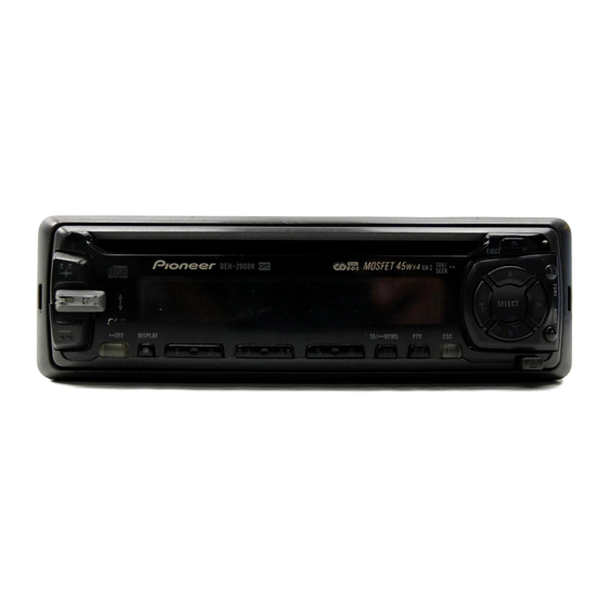
Head Unit Controls and Basic Functions
Identifies head unit controls and basic operations like source selection and volume.
Tuner Operation
Details manual tuning, seek tuning, and preset station management for the tuner.
CD Player Operation
Explains disc loading, eject, track search, and playback controls for the CD player.
Audio Adjustments
Covers equalizer settings, fader/balance, loudness, FIE, and source level adjustments.
SPECIFICATIONS
General and CD Player Specifications
Technical specifications for the general system and CD player functions.
Tuner Specifications
Technical specifications for FM, MW, and LW tuner performance and sensitivity.
Need help?
Do you have a question about the DEH-2030R and is the answer not in the manual?
Questions and answers