Table of Contents
Advertisement
DEFAULT INSTALLER CODE
0000 / 000000
DEFAULT SYSTEM MASTER CODE
1234 / 123456
HOW DO I ENTER PROGRAMMING MODE?
STEP 1: Press [
]
E N TE R
STEP 2: Enter your [
IN S T A LL E R C O D E
STEP 3: Enter 3-digit [
S E CT IO N
STEP 4: Enter required [
DECIMAL AND HEXADECIMAL PROGRAMMING TABLE
Value or Action
Values 1 to 9
A
(hexa only)
B
(hexa only)
C
(hexa only)
D
(hexa only)
E
(hexa only)
F
(hexa only)
Exit Without Saving
Erase Current Digit
Save Data
(hexa only)
TROUBLE DISPLAY
Press the [
] or [
T B L
T R BL
every 5 seconds whenever a new trouble condition has occurred. Press the [
[1] - No Battery or Low Battery
[2] - Wireless Transmitter Low Battery
[3] - Power Failure
[4] - Bell Output Disconnected
[5] - Maximum Bell Current
[6] - Maximum Auxiliary Current
[7] - Communicator Report Failure
* press the illuminated key ([9], [
Tamper troubles.
** press [8] to re-program the time.
1728EX, 1728, 1738EX
S
YSTEM
(see section [281] on page 17)
(see section [301] on page 17)
]
] you wish to program
]
D A T A
What Do I
Press?
[1] to [9]
[0]
[
]
ST AY
[
]
BYP
[
]
MEM
[
] / [
]
TBL
TRBL
1
[
] / [
]
PG
F NC
[
]
C LEAR
[
]
FORC E
[
]
ENT ER
] key to view the Trouble Display. Please note that the keypad can be programmed to emit a
] or [
]) to view which zones are causing the trouble. Enter the Installer Code to clear
ST AY
ME M
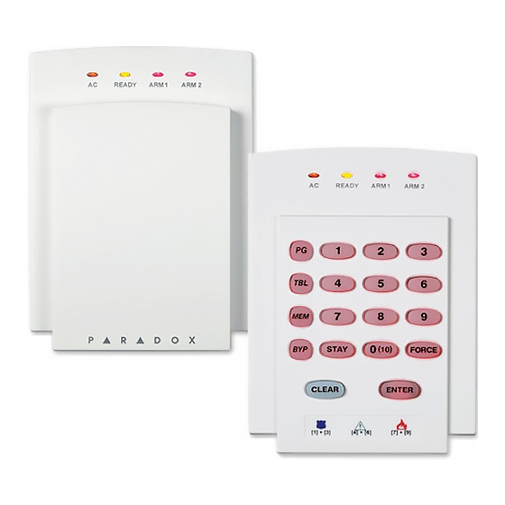
Spectra 1728/EX & 1738/EX
P
ROGRAMMING
Software Version 2.1
10-Zone LED
[1] to [9]
[0
]
(10)
[
]
STAY
[
]
BYP
[
]
M EM
[
]
T BL
[
]
PG
[
] flashes
[
E NT E R
A RM
Displays next digit or next section
Advances to the next section
[8] - Timer Loss**
[9] - Tamper or Zone Wiring Failure*
[10] - Telephone Line Monitoring Failure
[11]/[
] - Fire Loop Trouble*
S TA Y
[12]/[
] - Module Loss
B YP
[13]/[
] - Wireless Transmitter Supervision Loss*
M EM
[16]/[
] and [
F OR C E
- 1 -
Programming Guide
1738
AND
G
UIDE
What Do I See?
16-Zone LED
[1] to [9]
[10]
[11]
[12]
[13]
[14]
[15]
] & [
] flash
"SECTION [
1
1
ST AY
] or [
] key to stop the beeping.
T B L
T R B L
]/[
] flashes - Keypad Fault
T BL
T RB L
LCD
[1] to [9]
0
B
C
D
E
F
]"
BEEP
Advertisement
Table of Contents

Related Manuals for Spectra 1738


Summarization of Contents
Getting Started with Spectra Programming
Enter Programming Mode
Step-by-step guide on entering the system's programming mode using installer or master codes.
Decimal and Hexadecimal Programming Table
Reference table for decimal and hexadecimal values used in programming.
Trouble Display Codes
List of system trouble conditions and their codes for quick reference.
Keypad Configuration and Operation
Data Display Mode
Method to view programming one digit at a time on LED keypads.
Configure Keypads (V2.0 and Prior)
Steps to program zone number, EOL, and tamper switch for keypads.
Zone Programming
Zone Recognition Table
Table mapping detection devices to control panel inputs for zone assignments.
Zone Programming Details
Zone Programming Procedure
Steps to program zone definition, partition assignment, and zone options.
Zone Definition and Options
Details on zone definition types, partition assignment, and zone options.
System Timers
Zone Speed Timers
Settings for zone response time in milliseconds.
Event Timers Configuration
Configuration of system timers like entry/exit delays, bell cut-off, and PGM timers.
Programmable Outputs (PGMs)
PGM Activation and Deactivation Events
Defining events for PGM activation and deactivation using Event Groups and Sub-Groups.
System Options and Configuration
General System Options
Configuration of various system-wide settings and features.
Arming, Disarming, and Partition Options
Settings for arming, disarming, restrictions, and partition behavior.
Dialer and Communication Options
Configuration of dialer, TLM, and event call direction settings.
Communication and Reporting
Communication Settings
Selecting reporting formats and programming telephone numbers.
Report Codes Configuration
Assigning report codes for arming, disarming, alarm, and trouble events.
System Settings and User Codes
System Settings
Configuration of system real-time clock, installer code, and master code.
User Code Options and Management
Assigning permissions and options to user access codes.
Module Management and Data Transfer
Reprogramming Modules
Process to re-program expansion modules using saved settings.
Paradox Memory Key (PMC-3) Operations
Procedures for downloading to or copying from the Paradox Memory Key.
Bus Module Configuration: 4-Output
4-Output Bus Module (V2.0) Setup
Configuration options and PGM programming for the 4-output bus module.
Bus Module Configuration: Printer
Printer Bus Module (V2.0) Options
Configuring general options and zone status printing for the printer module.
Bus Module Configuration: Printer Settings
Serial and Parallel Port Setup
Configuring baud rates and port types for the printer module.
Clock Programming
Setting the date and time for the printer module.
Bus Module Configuration: Voice Module
Voice-Assisted Arm/Disarm Module (V2.0) Options
Configuration options for the voice-assisted arm/disarm module.
Bus Module Configuration: Wireless and Zone Expansion
Wireless Transmitter Zone Assignment
Assigning wireless transmitters to expansion inputs.
Wireless Module Options and PGM
Configuring wireless transmitter supervision and PGM activation/deactivation.
Remote Control Operation
Signal Strength and Assignment
Checking signal strength and assigning remote controls to users.
Button Options and Programming
Configuring button functions and assigning remote controls via sections [711]-[718].
Bus Module Configuration: Zone Expansion
Zone Expansion Module Options
Configuring EOL resistors and tamper recognition for zone expansion modules.
Zone Expansion Module Assignment and PGM
Assigning expansion inputs to zones and configuring PGM for expansion modules.
User Operation and Access Codes
Partitioning Overview
Explanation of how the partitioning feature divides the system.
User Access Code Management
Procedures for programming and deleting user access codes.
Keypad Features and Functions
Keypad Programming Features
How to program chime zones, mute keypads, and adjust backlight.
Quick Function Key Operations
Using quick function keys for installer test mode, reports, and WinLoad communication.
Appendix A: Ademco CID Report Codes (Programmatic)
Programmatic CID Report Code List
Hexadecimal values for Ademco Contact ID programmable report codes.
Appendix B: Ademco CID Report Codes (All Codes)
All CID Report Code List
Contact ID report codes for all system events.
Hardware Connections: Printer Module
Printer Bus Module Wiring
Wiring diagram and connection details for the APR3-PRT1 printer module.
Hardware Connections: Expansion Modules
4-Output Bus Module Wiring
Wiring diagram for the APR3-PGM4 4-output bus module.
4-Zone Expansion Bus Module Wiring
Wiring diagram for the SPC/APR3-ZX4 zone expansion module.
Hardware Connections: Voice Module
Voice-Assisted Arm/Disarm Module Wiring
Wiring diagram for the APR3-ADM2 voice-assisted module.
Hardware Connections: Wireless and Zone Expansion
8-Zone Expansion Bus Module Wiring
Wiring diagram for the SPC/APR3-ZX8 zone expansion module.
Omnia Wireless Receiver Wiring
Wiring diagram for the OMN-RCV3 wireless receiver.
Zone Input Wiring Diagrams
Single Zone Input Wiring
Diagrams for connecting single zone inputs with various EOL and tamper configurations.
Double Zone Input Wiring
Diagrams for connecting double zone inputs with ATZ option.
Special Circuit and Keypad Wiring
Fire Circuits, Keyswitches, and PGM Wiring
Wiring for fire circuits, keyswitches, and PGM outputs.
Multiple Keypad Connection Guidelines
Instructions for connecting multiple keypads to the control panel.
Control Panel PCB Layout and Power (Model 1728)
Spectra 1728EX/1728 PCB Diagram
Diagram of the Spectra 1728EX and 1728 control panel PCB.
Transformer and Power Requirements
Specifications for transformers and power supply requirements.
Control Panel PCB Layout and Power (Model 1738)
Spectra 1738EX/1738 PCB Diagram
Diagram of the Spectra 1738EX and 1738 control panel PCB.
Transformer and Power Requirements
Specifications for transformers and power supply requirements.
Document Notes
General Notes Section
Blank page for user notes.
Need help?
Do you have a question about the 1738 and is the answer not in the manual?
Questions and answers