Table of Contents
Advertisement
DEFAULT INSTALLER CODE
0000 / 000000
DEFAULT SYSTEM MASTER CODE
1234 / 123456
HOW DO I ENTER PROGRAMMING MODE?
STEP 1: Press [
]
E N TE R
STEP 2: Enter your [
IN S T A LL E R C O D E
STEP 3: Enter 3-digit [
S E CT IO N
STEP 4: Enter required [
DECIMAL AND HEXADECIMAL PROGRAMMING TABLE
Value or Action
Values 1 to 9
A
(hexa only)
B
(hexa only)
C
(hexa only)
D
(hexa only)
E
(hexa only)
F
(hexa only)
Exit Without Saving
Erase Current Digit
Save Data
(hexa only)
TROUBLE DISPLAY
Press the [
] or [
T B L
T R BL
every 5 seconds whenever a new trouble condition has occurred. Press the [
[1] - No Battery or Low Battery
[2] - Wireless Transmitter Low Battery
[3] - Power Failure
[4] - Bell Output Disconnected
[5] - Maximum Bell Current
[6] - Maximum Auxiliary Current
[7] - Communicator Report Failure
* press the illuminated key ([9], [
Tamper troubles.
** press [8] to re-program the time.
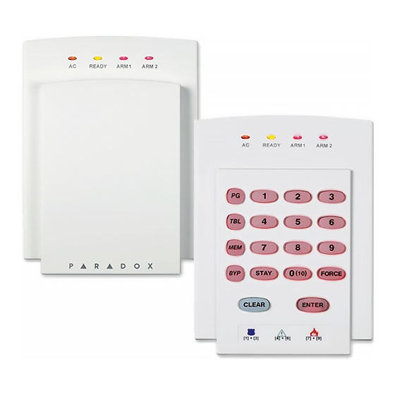
1728EX, 1728, 1738EX
S
YSTEM
(see section [281] on page 17)
(see section [301] on page 17)
]
] you wish to program
]
D A T A
What Do I
Press?
[1] to [9]
[0]
[
]
ST AY
[
]
BYP
[
]
MEM
[
] / [
]
TBL
TRBL
1
[
] / [
]
PG
F NC
[
]
C LEAR
[
]
FORC E
[
]
ENT ER
] key to view the Trouble Display. Please note that the keypad can be programmed to emit a
] or [
]) to view which zones are causing the trouble. Enter the Installer Code to clear
ST AY
ME M
Spectra 1728/EX & 1738/EX
P
ROGRAMMING
Software Version 2.1
10-Zone LED
[1] to [9]
[0
]
(10)
[
]
STAY
[
]
BYP
[
]
M EM
[
]
T BL
[
]
PG
[
] flashes
[
E NT E R
A RM
Displays next digit or next section
Advances to the next section
[8] - Timer Loss**
[9] - Tamper or Zone Wiring Failure*
[10] - Telephone Line Monitoring Failure
[11]/[
] - Fire Loop Trouble*
S TA Y
[12]/[
] - Module Loss
B YP
[13]/[
] - Wireless Transmitter Supervision Loss*
M EM
[16]/[
] and [
F OR C E
- 1 -
Programming Guide
1738
AND
G
UIDE
What Do I See?
16-Zone LED
[1] to [9]
[10]
[11]
[12]
[13]
[14]
[15]
] & [
] flash
"SECTION [
1
1
ST AY
] or [
] key to stop the beeping.
T B L
T R B L
]/[
] flashes - Keypad Fault
T BL
T RB L
LCD
[1] to [9]
0
B
C
D
E
F
]"
BEEP
Advertisement
Table of Contents

Subscribe to Our Youtube Channel
Related Manuals for Spectra 1728EX


Summary of Contents for Spectra 1728EX
-
Page 1: Default Installer Code
1728EX, 1728, 1738EX 1738 YSTEM ROGRAMMING UIDE Software Version 2.1 DEFAULT INSTALLER CODE 0000 / 000000 (see section [281] on page 17) DEFAULT SYSTEM MASTER CODE 1234 / 123456 (see section [301] on page 17) HOW DO I ENTER PROGRAMMING MODE? -
Page 2: Table Of Contents
TABLE OF CONTENTS Default Installer Code....................................1 Default System Master code ..................................1 How Do I Enter Programming Mode? ................................1 Decimal and Hexadecimal Programming Table............................1 Trouble Display ......................................1 Data Display Mode (LED Keypads Only) ..............................3 Configuring The 1686H, 1686V and 1689 Keypads (v2.0 or higher) ......................3 Configuring The 1686H, 1686V and 1689 Keypads (prior to V2.0)....................... -
Page 3: Data Display Mode (Led Keypads Only)
EOL resistor. When key [2] is ON (illuminated), EOL is enabled and the keypad zone requires that an external EOL resistor be connected (refer to “Spectra 1728EX and 1728 PCB Layout” on page 38 and “Spectra 1738EX and 1738 PCB Layout”... -
Page 4: Configuring The 1686H, 1686V And 1689 Keypads (Prior To V2.0)
EOL resistor. When the jumper is ON, EOL is enabled and the keypad zone requires that an external EOL resistor be connected (refer to “Spectra 1728EX and 1728 PCB Layout” on page 38 and “Spectra 1738EX and 1738 PCB Layout”... - Page 5 Only the control panel’s on-board inputs can be defined as a Fire, Delayed Fire or a Keyswitch zone. In the 1728EX and 1728 the on-board zones are zones 01 to 05 and in the 1738EX and 1738 the on-board zones are zones 01 to 07.
-
Page 6: System Timers
___/___ : ___/___ hours (00 to 23) : minutes (00 to 59) Disabled AU T O A R M T IM E PA R TI T ION * Maximum 60 seconds for UL listed systems. ** 5 minutes minimum for ULC installations. Spectra 1728/EX & 1738/EX - 6 - Programming Guide... -
Page 7: Programmable Outputs
99 = Any Remote Control 08 = Button Pressed on Remote 01 to 08 = Remote Controls 1 to 8 (see button option “C” on page 24) 99 = Any Remote Control Spectra 1728/EX & 1738/EX - 7 - Programming Guide... - Page 8 26 = Zone Tamper 01 to 16 = Zones 1 to 16 99 = Any Zone 27 = Zone Tamper Restore 01 to 16 = Zones 1 to 16 99 = Any Zone Spectra 1728/EX & 1738/EX - 8 - Programming Guide...
- Page 9 99 = Any Zone Event Group # Sub-Group # Partition # 80 = PGM follows Clock (APR3-PGM4 only) HH = hour according to 24hr. clock MM = minutes according to 24hr. clock Spectra 1728/EX & 1738/EX - 9 - Programming Guide...
-
Page 10: System Options
* Reassign Zones to Expansion Inputs changes the zone numbering to increase the number of expansion inputs that can be displayed on 10-Zone LED Keypads. Refer to 1728EX, 1728, 1738EX and 1738 Reference & Installation Manual for details. SECTION [127]: General Options... - Page 11 When armed: Follows Z one Alarm Types When disarmed: GE NE RA TE S A UDI BL E A LA RM When armed: Follows Z one Alarm Types * Not to be used with UL installations. Spectra 1728/EX & 1738/EX - 11 - Programming Guide...
- Page 12 Dialing Method Pulse Dialing Tone (DTMF) Dialing Pulse Ratio 1:1.5 If armed, activate bell output on Com. Failure Disabled Enabled Future Use Future Use * Not to be used with UL installations. Spectra 1728/EX & 1738/EX - 12 - Programming Guide...
- Page 13 Enabled for Trouble/Restore Report Codes Call Telephone #1 Disabled Enabled for Special Report Codes Call Telephone #2 Disabled Enabled for Special Report Codes Future Use Future Use Future Use Future Use Spectra 1728/EX & 1738/EX - 13 - Programming Guide...
-
Page 14: Communication Settings
T B L T RB L FN C * UL Note: The installer is required to verify the complete compatibility of the DAC Receiver and formats at least once per year. Spectra 1728/EX & 1738/EX - 14 - Programming Guide... -
Page 15: Report Codes
___/___Access Code 16 ___/___Access Code 36 ___/___N/A [178]___/___Access Code 17 [183]___/___Access Code 37 ___/___Access Code 18 ___/___Access Code 38 ___/___Access Code 19 ___/___Access Code 39 ___/___Access Code 20 ___/___Access Code 40 Spectra 1728/EX & 1738/EX - 15 - Programming Guide... - Page 16 ___/___Fire Loop Trouble ___/___N/A [207]___/___Wireless Low Battery [210]___/___Wireless Low Battery [213]___/___TX Supervision Loss ___/___Module Fault ___/___Module Fault ___/___TX Supervision Restore ___/___Printer Fault ___/___Printer Fault ___/___N/A ___/___Fail to Communicate ___/___Fail to Communicate ___/___N/A Spectra 1728/EX & 1738/EX - 16 - Programming Guide...
-
Page 17: System Settings
1 2 3 4 5 6 7 8 [347] User Code 047 1 2 3 4 5 6 7 8 [348] User Code 048 1 2 3 4 5 6 7 8 Spectra 1728/EX & 1738/EX - 17 - Programming Guide... -
Page 18: Reprogram All Modules
1) Remove AC and battery power from the control panel. 2) Insert Memory Key onto the serial connector labelled on the Spectra control panel that you want to copy. Make sure the write protect jumper of the Memory Key is on. -
Page 19: 4-Output Bus Module V2.0
Each PGM Deactivation event can be used as another activation event if their respective PGM timer (see sections [501] to [504]) is programmed with a value other than 000. The APR3-PGM4 uses the same PGM events as the Spectra control panel, please refer to “Programmable Outputs”... -
Page 20: Printer Bus Module V2.0
PRINTER BUS MODULE V2.0 Due to the APR3-PRT1’s Auto-recognition feature, it can be used with either the Spectra (V2.0 or higher), Digiplex or DigiplexNE control panel. When connected to the bus, the APR3-PRT1 automatically detects which control panel it is connected to and adjusts its internal communication parameters to function accordingly. - Page 21 The PGM Deactivation event can be used as another activation event if the PGM Timer (section [554]) is programmed with a value other than 000. The PRT1 module uses the same PGM events as the Spectra control panel, please refer to “Programmable Outputs ”...
-
Page 22: Voice-Assisted Arm/Disarm Bus Module V2.0
VOICE-ASSISTED ARM/DISARM BUS MODULE V2.0 Due to InTouch’s Auto-recognition feature, it can be used with either the Spectra (V2.0 or higher), Digiplex or DigiplexNE control panel. When connected to the bus, InTouch automatically detects which control panel it is connected to and adjusts its internal communication parameters to function accordingly. -
Page 23: Wireless Bus Modules
WIRELESS BUS MODULES Only one OMN-RCV3 (Omnia) can be connected to each Spectra control panel. ZONE ASSIGNMENT The serial number can be located on the inside of the transmitter or you can use the Serial Number Display feature (see page 23). Also, refer to “Zone Recognition Table” on page 4. - Page 24 ___/___/___(001-048 = user #) remote control #8 - section [728]/[738]* * refer to “Remote Control Assignment” on page 25. BUTTON OPTIONS * Only arming and disarming button functions were investigated by UL. Spectra 1728/EX & 1738/EX - 24 - Programming Guide...
- Page 25 R EM OT E C ON T R OL [736] R EM OT E C ON T R OL [737] R EM OT E C ON T R OL [738] R EM OT E C ON T R OL Spectra 1728/EX & 1738/EX - 25 - Programming Guide...
-
Page 26: Zone Expansion Bus Modules
SPC-ZX4 version 1.0, APR3-ZX4 version 1.0, SPC-ZX8 version 1.0 and APR3-ZX8 version 2.0. Modules with the APR- prefix are compatible with Spectra (versions 2.0 and higher) and Digiplex. Modules with the APR3- prefix are compatible with Spectra (versions 2.0 and higher), Digiplex and DigiplexNE. -
Page 27: User Operation
USER OPERATION PARTITIONING The Spectra system is equipped with a partitioning feature which can divide the alarm system into two distinct areas identified as Partition 1 and Partition 2. Partitioning can be used in installations where shared security systems are more practical, such as an office/warehouse building. - Page 28 ] + [ E NT E R I NS TA L L ER MA S TE R C OD E FO RC E Forces the control panel to pick-up an incoming telephone call. Spectra 1728/EX & 1738/EX - 28 - Programming Guide...
-
Page 29: Appendix A - Ademco Cid Report Code List (Prog.)
RF xmtr. Low Battery Program Mode Entry Fire Supervisory OPEN/CLOSE - 400 Program Mode Exit Low Water Pressure Open/Close Exception Schedule Change Low CO2 O/C by User Gate Valve Sensor Group O/C Spectra 1728/EX & 1738/EX - 29 - Programming Guide... -
Page 30: Appendix B - Ademco Cid Report Code List (All Codes)
AC Failure 1 3A1 - AC loss Battery Failure 1 3A9 - Battery test failure Auxiliary supply trouble 1 3AA - System trouble Bell output current limit 1 321 - Bell 1 Spectra 1728/EX & 1738/EX - 30 - Programming Guide... - Page 31 1 6A2 - Periodic test report PC software communication finished 1 412 - Successful - download access Installer on site 1 627 - Program mode Entry Installer programming finished 1 628 - Program mode Exit Spectra 1728/EX & 1738/EX - 31 - Programming Guide...
-
Page 32: Bus Module Connections
BUS MODULE CONNECTIONS PRINTER BUS MODULE (APR3-PRT1) Spectra 1728/EX & 1738/EX - 32 - Programming Guide... - Page 33 4-OUTPUT BUS MODULE (APR3-PGM4) 4-ZONE EXPANSION BUS MODULE (SPC-ZX4 AND APR3-ZX4) Spectra 1728/EX & 1738/EX - 33 - Programming Guide...
- Page 34 VOICE-ASSISTED ARM/DISARM BUS MODULE (APR3-ADM2) Spectra 1728/EX & 1738/EX - 34 - Programming Guide...
- Page 35 8-ZONE EXPANSION BUS MODULES (SPC-ZX8 AND APR3-ZX8) OMNIA WIRELESS RECEIVER (OMN-RCV3) Spectra 1728/EX & 1738/EX - 35 - Programming Guide...
-
Page 36: Hardware Connections
HARDWARE CONNECTIONS SINGLE ZONE INPUTS DOUBLE ZONE INPUTS (with ATZ option only) Spectra 1728/EX & 1738/EX - 36 - Programming Guide... - Page 37 Spectra Control Panels Reference & Installation manual. When a 1641 LCD keypad is connected to Spectra, the Keypad Zone Sending option (Option [2] key [1]) determines whether the status of the keypad zone will be transmitted to the control panel. Refer to the 1641 Installer’s Guide for more info.
- Page 38 Inputs” on page 36. For the keypad’s zone, EOL and tamper configurations, refer to page 3. For UL Listed warnings, refer to the UL and ULC Warnings section in the Spectra Reference & Installation Manual. Transformer Requirements Table Transformer: Amseco XP-1620...
- Page 39 1738” on page 37. For the keypad’s zone, EOL and tamper configurations, refer to page 3. For UL Listed warnings, refer to the UL and ULC Warnings section in the Spectra Reference & Installation Manual. Transformer Requirements Table Transformer: Amseco XP-1620 Rec: 16.5VAC 40VA...
- Page 40 NOTES 04/2003 17X8-EP10 PRI NTE D I N CANA DA...
Need help?
Do you have a question about the 1728EX and is the answer not in the manual?
Questions and answers