Table of Contents
Advertisement
Quick Links
Default Installer Code
0000 / 000000
Default System Master Code
1234 / 123456
How Do I Enter Programming Mode?
1) Press [
].
ENTER
2) Enter your [
INSTALLER CODE
3) Enter 3-digit [
SECTION
4) Enter required [
DATA
Decimal and Hexadecimal Programming Table
Value or Action
Values 1 to 9
A
(hex only)
B
(hex only)
C
(hex only)
D
(hex only)
E
(hex only)
F
(hex only)
Exit Without Saving
Erase Current Digit
Save Data
(hex only)
Trouble Display
Press the [
] or [
TBL
TRBL
every 5 seconds whenever a new trouble condition has occurred. Press the [
[1] - No Battery or Low Battery
[2] - Wireless Transmitter Low Battery
[3] - Power Failure
[4] - Bell Output Disconnected
[5] - Maximum Bell Current
[6] - Maximum Auxiliary Current
[7] - Communicator Report Failure
* Press the illuminated key ([9], [
Tamper troubles.
** Press [8] to re-program the time.
System Programming Guide
(see section [281] on page 18)
(see section [301] on page 18)
].
] you wish to program.
].
What Do I
Press?
[1] to [9]
[0]
[
]
STAY
[
]
BYP
[
]
MEM
[
] / [
TBL
TRBL
1
[
] / [
]
PG
FNC
[
]
CLEAR
[
]
FORCE
[
]
ENTER
] key to view the Trouble Display. Please note that the keypad can be programmed to emit a
] or [
]) to view which zones are causing the trouble. Enter the Installer Code to clear
STAY
MEM
Spectra 1759MG
1759MG
Software Version 2.0
10-Zone LED
[1] to [9]
[0
]
(10)
[
]
STAY
[
]
BYP
[
]
MEM
]
[
]
TBL
[
]
PG
[
] flashes
[
ENTER
ARM
Displays next digit or next section
Advances to the next section
[8] - Timer Loss**
[9] - Tamper or Zone Wiring Failure*
[10] - Telephone Line Monitoring Failure
[11]/[
] - Fire Loop Trouble*
STAY
[12]/[
] - Module Loss
BYP
[13]/[
] - Wireless Transmitter Supervision Loss*
MEM
[16]/[
] and [
FORCE
- 1 -
Programming Guide
What Do I See?
16-Zone LED
[1] to [9]
[10]
[11]
[12]
[13]
[14]
[15]
] & [
] flash
"SECTION [
1
1
STAY
] or [
] key to stop the beeping.
TBL
TRBL
]/[
] flashes - Keypad Fault
TBL
TRBL
LCD
[1] to [9]
0
B
C
D
E
F
]"
BEEP
Advertisement
Table of Contents

Related Manuals for Spectra 1759MG


Summary of Contents for Spectra 1759MG
-
Page 1: Default Installer Code
* Press the illuminated key ([9], [ ] or [ ]) to view which zones are causing the trouble. Enter the Installer Code to clear STAY Tamper troubles. ** Press [8] to re-program the time. Spectra 1759MG - 1 - Programming Guide... -
Page 3: Table Of Contents
Appendix B - Ademco CID Report Code List (All Codes) .............. 31 Bus Module Connections ......................... 32 Printer Module (APR3-PRT1)............................32 4-PGM Output Module (APR3-PGM4) ......................... 33 4-zone expansion Bus Module (SPC-ZX4 and APR3-ZX4) ..................33 Spectra 1759MG - 3 - Programming Guide... - Page 4 Programming a Wireless Fire Zone ..........................36 Alarm Relay and PGM Connections ..........................37 Connecting More Than Two Keypads........................... 37 AC Power & Backup Battery Connections ........................37 Spectra 1759MG PCB Layout............................38 Spectra 1759MG - 4 - Programming Guide...
-
Page 5: Data Display Mode (Led Keypads Only)
EOL resistor. When key [2] is ON (illuminated), EOL is enabled and the keypad zone requires that an external EOL resistor be connected (refer to Spectra 1759MG PCB Layout on page 38 for more details). Key [2] OFF - EOL disabled... -
Page 6: Zone Programming
Input 8 = Zone 15 Zone 14 Zone 12 Zone 11 = not displayed on 10-Zone LED Keypads Option [7] = Reassign Keypad Zone 2 Option [8] = Reassign zones to expansion inputs Spectra 1759MG - 6 - Programming Guide... - Page 7 Only the control panel’s on-board inputs can be defined as a Fire, Delayed Fire or a Keyswitch zone. The on-board zones are zones 01 to 05. To program a wireless fire zone, refer to Programming a Wireless Fire Zone on page 36. Spectra 1759MG - 7 - Programming Guide...
-
Page 8: System Timers
___/___ : ___/___ hours (00 to 23) : minutes (00 to 59) Disabled AUTO ARM TIME PARTITION [112] ___/___ : ___/___ hours (00 to 23) : minutes (00 to 59) Disabled AUTO ARM TIME PARTITION Spectra 1759MG - 8 - Programming Guide... -
Page 9: Programmable Outputs
(see button option “B” on page 25) 99 = Any Remote Control 08 = Button Pressed on Remote 01 to 08 = Remote Controls 1 to 8 (see button option “C” on page 25) 99 = Any Remote Control Spectra 1759MG - 9 - Programming Guide... - Page 10 26 = Zone Tamper 01 to 15 = Zones 1 to 15 99 = Any Zone 27 = Zone Tamper Restore 01 to 15 = Zones 1 to 15 99 = Any Zone Spectra 1759MG - 10 - Programming Guide...
- Page 11 01 to 15 = Zones 1 to 15 99 = Any Zone Event Group # Sub-Group # Partition # 80 = PGM follows Clock (APR3-PGM4 only) HH = hour according to 24hr. clock MM = minutes according to 24hr. clock Spectra 1759MG - 11 - Programming Guide...
-
Page 12: System Options
* Reassign Keypad Zone 2 and Reassign zones to expansion inputs change the zone numbering to increase the number of expansion inputs that can be displayed on 10-Zone LED Keypads. Refer to the Zone Recognition Table on page 6 and the Spectra 1759MG Reference & Installation Manual for details. Section [127]: General Options... - Page 13 When disarmed: GENERATES TROUBLE ONLY When armed: Follows Zone Alarm Types When disarmed: GENERATES SILENT ALARM When armed: Follows Zone Alarm Types When disarmed: GENERATES AUDIBLE ALARM When armed: Follows Zone Alarm Types Spectra 1759MG - 13 - Programming Guide...
- Page 14 2 calls to pager or cellular telephone 3 calls to pager or cellular telephone 4 calls to pager or cellular telephone Pager Format Transmission Options Transmit report code Transmit report code after Pager delay immediately Spectra 1759MG - 14 - Programming Guide...
-
Page 15: Communication Settings
] = Switch from pulse to tone dialing or vice versa ] = Delete current digit STAY FORCE ] = # ] or [ ] = 4-second pause ] or [ ] = Inserts Blank Space TRBL FNC1 Spectra 1759MG - 15 - Programming Guide... -
Page 16: Report Codes
___/___Keyswitch Disarm ___/___Access Code 16 ___/___Access Code 36 ___/___N/A [178]___/___Access Code 17 [183]___/___Access Code 37 ___/___Access Code 18 ___/___Access Code 38 ___/___Access Code 19 ___/___Access Code 39 ___/___Access Code 20 ___/___Access Code 40 Spectra 1759MG - 16 - Programming Guide... - Page 17 ___/___Fire Loop Trouble ___/___Fire Loop Trouble ___/___N/A [207]___/___Wireless Low Battery [210]___/___Wireless Low Battery [213]___/___TX Supervision Loss ___/___Module Fault ___/___Module Fault ___/___TX Supervision Restore ___/___Printer Fault ___/___Printer Fault ___/___N/A ___/___Fail to Communicate ___/___Fail to Communicate ___/___N/A Spectra 1759MG - 17 - Programming Guide...
-
Page 18: System Settings
User Code 024 1 2 3 4 5 6 7 8 [347] User Code 047 1 2 3 4 5 6 7 8 [348] User Code 048 1 2 3 4 5 6 7 8 Spectra 1759MG - 18 - Programming Guide... -
Page 19: Reprogram All Modules
1) Remove AC and battery power from the control panel. 2) Insert the Memory Key onto the serial connector labelled on the Spectra control panel to which you wish to download the contents of the memory key to. 3) Re-apply AC and battery power. -
Page 20: 4-Pgm Output Modules V2.0
Each PGM Deactivation event can be used as another activation event if their respective PGM timer (see sections [501] to [504]) is programmed with a value other than 000. The APR3-PGM4 uses the same PGM events as the Spectra control panel, please refer to Programmable Outputs on page 9. -
Page 21: Printer Module V2.0
Printer Module V2.0 Due to the APR3-PRT1’s Auto-recognition feature, it can be used with either the Spectra (V2.0 or higher), DGP-848 or DGP-NE96 control panel. When connected to the bus, the APR3-PRT1 automatically detects which control panel it is connected to and adjusts its internal communication parameters to function accordingly. Only one APR3-PRT1 can be connected to each Spectra control panel. -
Page 22: Pgm Programming
The PGM Deactivation event can be used as another activation event if the PGM Timer (section [554]) is programmed with a value other than 000. The APR3-PRT1 module uses the same PGM events as the Spectra control panel, please refer to Programmable Outputs on page 9. -
Page 23: Voice-Assisted Arm/Disarm Bus Module V2.0
Voice-assisted Arm/Disarm Bus Module V2.0 Due to InTouch’s Auto-recognition feature, it can be used with either the Spectra (V2.0 or higher), DGP-848 or DGP-NE96 control panels. When connected to the bus, InTouch automatically detects which control panel it is connected to and adjusts its internal communication parameters to function accordingly. -
Page 24: Wireless Features
Wireless Features Do not cut, bend or alter 1759MG’s antennae and ensure that electrical wires do not cross over the antennae, as this may affect signal reception. Zone Assignment The serial number can be located on the inside of the transmitter or you can use the Serial Number Display feature (see page 24). -
Page 25: Remote Control User Assignment
_____/_____/_____/_____/______/_____/_____/______ [711] _____/_____/_____/_____/______/_____/_____/______ [712] _____/_____/_____/_____/______/_____/_____/______ [713] _____/_____/_____/_____/______/_____/_____/______ [714] _____/_____/_____/_____/______/_____/_____/______ [715] _____/_____/_____/_____/______/_____/_____/______ [716] _____/_____/_____/_____/______/_____/_____/______ [717] _____/_____/_____/_____/______/_____/_____/______ [718] = These button combinations are not available with the MG-REM1or MG-RAC1 remote controls and cannot be programmed. Spectra 1759MG - 25 - Programming Guide... -
Page 26: Remote Control Assignment
[ ] button. FORCE Section # [731] REMOTE CONTROL [732] REMOTE CONTROL [733] REMOTE CONTROL [734] REMOTE CONTROL [735] REMOTE CONTROL [736] REMOTE CONTROL [737] REMOTE CONTROL [738] REMOTE CONTROL Spectra 1759MG - 26 - Programming Guide... -
Page 27: Zone Expansion Bus Modules
SPC-ZX4 version 1.0, APR3-ZX4 version 1.0, SPC-ZX8 version 1.0 and APR3-ZX8 version 2.0. Modules with the APR- prefix are compatible with Spectra (versions 2.0 and higher) and DGP-848. Modules with the APR3- prefix are compatible with Spectra (versions 2.0 and higher), DGP-848 and DGP-NE96. -
Page 28: User Operation
Partitioning The Spectra system is equipped with a partitioning feature which can divide the alarm system into two distinct areas identified as Partition 1 and Partition 2. Partitioning can be used in installations where shared security systems are more practical, such as an office/warehouse building. -
Page 29: Programming Chime Zones
Cancels all communication until the next reportable event. If the Master Code was used, only communication with WinLoad would be cancelled. Answer WinLoad Software ] + [ ] + [ ENTER INSTALLER MASTER CODE FORCE Forces the control panel to pick-up an incoming telephone call. Spectra 1759MG - 29 - Programming Guide... -
Page 30: Appendix A - Ademco Cid Report Code List (Prog.)
FIRE SUPERVISORY - 200 & 210 Sensor Tamper Program Mode Entry Fire Supervisory RF xmtr. Low Battery Program Mode Exit Low Water Pressure OPEN/CLOSE - 400 Exception Schedule Change Low CO2 Open/Close System Inactivity Spectra 1759MG - 30 - Programming Guide... -
Page 31: Appendix B - Ademco Cid Report Code List (All Codes)
Zone tampered (##) 1 144 - Sensor tamper Zone tamper restore (##) 3 144 - Sensor tamper restore AC Failure 1 3A1 - AC loss Battery Failure 1 3A9 - Battery test failure Spectra 1759MG - 31 - Programming Guide... -
Page 32: Bus Module Connections
Remove AC power and battery before adding APR3-PRT1 to the system. Do not connect any modules more than 76m (250ft) from the control panel. Only one Printer Module can be connected per Spectra control panel. Spectra 1759MG... -
Page 33: 4-Pgm Output Module (Apr3-Pgm4)
Remove AC and battery power from the control panel before connecting the module to the communication bus. Do not connect the APR3-ZX4 or SPC-ZX4 more than 76m (250ft) from the control panel. Only one APR3-ZX4 or one SPC-ZX4 can be connected per Spectra control panel. Spectra 1759MG... -
Page 34: Voice-Assisted Arm/Disarm Bus Module (Apr3-Adm2)
Remove AC and battery power from the control panel before adding the APR3-ADM2 module to the system. Do not connect the APR3-ADM2 more than 76m (250ft) from the control panel. Only one APR3- ADM2 can be connected per Spectra control panel. Green "PULSE"LED: Monitors the dialer. -
Page 35: 8-Zone Expansion Bus Modules (Spc-Zx8 And Apr3-Zx8)
Flash once every sec. = normal. Not Used Flash 1 sec. on & 1 sec. off = Trouble and/or communication failure. Inset 2 Refer to the Spectra 1759MG Reference & Installation Manual Not Used about connecting devices to the Expansion Input Terminals. Inset 1... -
Page 36: Hardware Connections
(see page 7). using Ademco Contact I.D., set the Contact ID Options from All Codes to Programmable (section [136] option [3] = OFF) and then enter the report code manually (see page 14). Spectra 1759MG - 36 - Programming Guide... -
Page 37: Alarm Relay And Pgm Connections
Spectra 1759MG Reference & Installation Manual. When a 1641 LCD keypad is connected to Spectra, the Keypad Zone Sending option (Option [2] key [1]) determines whether the status of the keypad zone will be transmitted to the control panel. Refer to the 1641 Installer’s Guide for more information. -
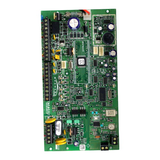
Page 38: Spectra 1759Mg Pcb Layout
This equipment must be installed and maintained by control panel. qualified service personnel only. For UL and C-UL warnings, refer to the UL and C-UL Warnings section at the back of the Spectra 1759MG Reference & Installation Manual. Spectra 1759MG... - Page 39 US patents may apply: 6215399, 6111256, 5751803, 5721542, 5287111, 5119069, 5077549, 5920259 and 5886632. Canadian and international patents may also apply. Spectra, Digiplex and Magellan are trademarks or registered trademarks of Paradox Security Systems Ltd. or its affiliates in Canada, the United States and/or other countries.
- Page 40 8:00 a.m. to 8:00 p.m. EST. For technical support outside Canada and the U.S., call 00-1-450-491-7444, Monday to Friday from 8:00 a.m. to 8:00 p.m. EST. Please feel free to visit our website at www.paradox.ca. 780 Industriel Blvd., Saint-Eustache (Quebec) J7R 5V3 CANADA Tel.: (450) 491-7444 Fax: (450) 491-2313 www.paradox.ca PRINTED IN CANADA - 01/2005 1759MG-EP05...
Need help?
Do you have a question about the 1759MG and is the answer not in the manual?
Questions and answers