Table of Contents
Advertisement
Quick Links
Download this manual
See also:
Programming Manual
Advertisement
Table of Contents

Related Manuals for Spectra 1759EX


Summary of Contents for Spectra 1759EX
- Page 1 1759EX V1.0 & I EFERENCE NSTALLATION ANUAL (433MH / 868MH 1759EX...
-
Page 3: Table Of Contents
TABLE OF CONTENTS Introduction..............2 Central Station Telephone Numbers ............31 Partition Account Numbers............... 31 Features ..................... 2 Reporting Formats..................31 Specifications ..................... 2 Pager Delay....................33 Installation ..............3 Event Call Direction .................. 33 Dialing Method..................33 Location and Mounting ................3 Pulse Ratio .................... -
Page 4: Introduction
• 2 on-board, fully programmable outputs (PGMs) and one 5A alarm relay • Simple, direct and logical programming • Event Call Direction: The Spectra 1759EX control panel events are divided into 5 groups of events. Each of these event groups can be programmed with a separate dialing sequence. -
Page 5: Installation
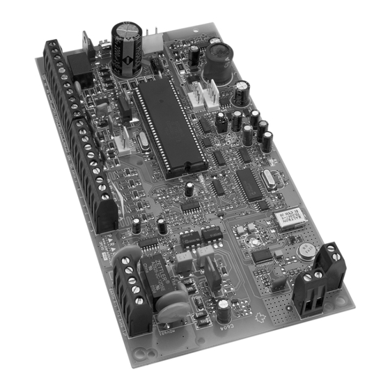
Avoid installing the 1759EX in the basement. Do not cut, bend or alter the antennae and ensure that electrical wires do not cross over the antennae as these may affect the signal reception. - Page 6 Figure 2.2: Spectra 1759EX Control Panel Overview Warning: Do not cut, bend or alter the antennae & ensure that electrical wires do not cross over the Refer to AC Power antennae as these and Backup Battery may affect the signal Connections on reception.
-
Page 7: Auxiliary Power Terminals
The Spectra 1759EX control panel also has a 5A relay. This relay can be connected as shown in Figure 2.3 on page 6. The Alarm Relay can be programmed to follow the bell output or the activation and deactivation of the Global PGM (see Alarm Relay Options on page 36). -
Page 8: Single Zone Inputs
Detection devices such as motion detectors and door contacts are connected to the control panel's zone input terminals. Figure 2.4 (below) demonstrates single zone input terminal connections recognized by Spectra. Once connected, the associated zone's parameters must be defined. For details refer to Zone Programming on page 13. -
Page 9: Keyswitch Connections
Figure 2.5: Keypad Zone Connections When a 1641 LCD keypad is connected to Spectra, the Keypad Zone Sending option (Option [2] key [1]) determines whether the status of the keypad zone will be transmitted to the control panel. The Keypad Zone Sending option of the 1641 keypad must be enabled during the following conditions: •... -
Page 10: Programming Methods
Decimal values from 000 to 255. Other sections will require that you enter Hexadecimal values from 0 to F. The required data will be clearly indicated in this manual as well as in the Spectra 1759EX Programming Guide. When entering the final digit in a section, the control panel will automatically save and advance to the next section. -
Page 11: Configuring The Led Keypads
EOL resistor. When key [2] is ON (illuminated), EOL is enabled and the keypad zone requires that an external EOL resistor be connected (refer to Spectra 1759EX Control Panel Overview on page 4 for more details). -
Page 12: Programming Using A Paradox Memory Key
PROGRAMMING USING A PARADOX MEMORY KEY* Copy the sections of one Spectra control panel into the Paradox Memory Key (PMC-3). Then copy the contents of the Memory Key into as many Spectra control panels as needed. Each panel is programmed in less than 3 seconds. -
Page 13: Access Codes
PART 4: ACCESS CODES The Spectra 1759EX control panel supports the following access codes: INSTALLER CODE: Used to program all control panel settings except User Access Codes. SYSTEM MASTER CODE (001) Provides full access. Arm and disarm using any method described in the User Code Options in section 4.4 as well as program the User Access Codes. -
Page 14: Lock Master Code
4.4.2 ARTITION SSIGNMENT Sections [302] to [348]: User Codes 002 to 048 Option [2] OFF = Deny access to partition 2 (default) Option [2] ON = User code has access to partition 2 If the system is partitioned (see page 37), user codes with this option enabled can arm and disarm partition 2. If the system is not partitioned, the control panel ignores this option. -
Page 15: Zone Programming
PART 5: ZONE PROGRAMMING The Spectra 1759EX control panel’s zone assignment depends on where the detection devices are connected (see Table 4). Table 4: Zone Recognition Table Device connected to 1759EX which input? Control Panel Input 1 = Zone 1... -
Page 16: Reassign Zones To Expansion Inputs
Option [8]: ON and Option [8]: ON and Option [8]: Option [8]: Option [7]: OFF Option [7]: ON (Reassign Keypad Zone 2) (Reassign Keypad Zone 2) 1759EX 1759EX 1759EX 1759EX Control Panel Input 1 = Zone 1 Zone 1 Zone 1... -
Page 17: Zone Definitions
Figure 5.1: Spectra Zone Programming [001] = Zone 1 [009] = Zone 9 [002] = Zone 2 [010] = Zone 10 [003] = Zone 3 [011] = Zone 11 Press the [004] = Zone 4 [012] = Zone 12 ] key... -
Page 18: Exclusive Zone Definitions
5.5.3 OLLOW ONES Sections [001] to [015]: Zones 1 to 15, First Digit = 3 When an armed Follow Zone opens, the control panel will immediately generate an alarm, unless an Entry Delay zone opens first: • If an armed Follow Zone opens after an Entry Delay zone opens, the control panel waits until the Entry Delay Timer has elapsed before generating an alarm. -
Page 19: Zone Partition Assignment
When the conditions for an alarm are met, the control panel can transmit the appropriate Zone Alarm report code (see page 29) and will not activate the control panel’s bell output. The appropriate LED on the keypads will STATUS flash to indicate an alarm and the user will still have to disarm the system. 1759EX PECTRA... -
Page 20: Zone Speed
[4] ON / [5] ON: Report Only When the conditions for an alarm have been met, the control panel can transmit the appropriate Zone Alarm report code (see page 29). The system will not have to be disarmed. 5.8.5 NTELLIZONE Sections [001] to [015]: Zones 1 to 15 Option [6] OFF = Intellizone Disabled (default) Option [6] ON... -
Page 21: Wireless Features
PART 6: WIRELESS FEATURES The Spectra 1759EX allows for the addition of up to eight fully supervised Omnia wireless transmitters, and up to eight programmable remote controls. WIRELESS TRANSMITTER PROGRAMMING The programming of the wireless transmitters (detectors and door contacts) is accomplished in two steps: 1. -
Page 22: Serial Number Display
Settings on page 21) to confirm their presence and functionality. If a device has not sent a signal within that time period, the Spectra 1759EX can generate a trouble, an alarm, and/or transmit a report code to the monitoring station (refer to Wireless Transmitter Supervision Options on page 40). -
Page 23: Remote Control Programming
When the battery voltage of a wireless transmitter (motion detector or door contact) drops below a certain value, the Spectra 1759EX will send a low battery report code to the monitoring station, and a trouble will appear in the keypad’s trouble display. - Page 24 001 to 048. Enter the desired User Number in a section from [701] to [708] that represent the remote control assigned in sections [731] to [738] (refer to Assigning a Remote Control to the Spectra 1759EX on page 21). For example, the remote control assigned in section [731] will be assigned to the User Access Code designated in section [701].
- Page 25 [D] = Activates any PGMs that have Event Group #09* as their Activation Event * Event Group #07, #08 and #09 (Button Pressed on Remote) of the Spectra 1759EX PGM Table. For the PGM Table, please refer to the Spectra 1759EX Programming Guide (1759EX-EP).
-
Page 26: Arming And Disarming Options
PART 7: ARMING AND DISARMING OPTIONS SWITCH TO STAY ARMING Section [133] = Partition 1, Section [134] = Partition 2 Option [4] OFF = Switch to Stay Arming Disabled (default) Option [4] ON = Switch to Stay Arming Enabled If a user Regular arms a partition, but does not exit through (open and close) an Entry Delay zone during the Exit Delay, the control panel can be programmed to switch from Regular Arming to Stay Arming. -
Page 27: No Movement Auto-Arming
When enabled, the keypad will beep once every second during the Exit Delay and will beep rapidly during the final 10 seconds of the Exit Delay. 7.10.1 ELAY Section [130]: Arming/Disarming Options Option [8] OFF = Beep on Exit Delay Disabled Option [8] ON = Beep on Exit Delay Enabled (default) 1759EX PECTRA... -
Page 28: Bell Squawk On Arm/Disarm With Keypad
7.11 BELL SQUAWK ON ARM/DISARM WITH KEYPAD Section [130]: Arming/Disarming Options Option [7] OFF = Bell Squawk on Arm/Disarm Disabled (default) Option [7] ON = Bell Squawk on Arm/Disarm Enabled When this feature is enabled, the bell or siren will squawk once upon arming and twice upon disarming. 7.12 BELL SQUAWK ON ARM/DISARM WITH REMOTE CONTROL Section [131]: Arming/Disarming Options... -
Page 29: Keypad Panic Options
In section [094] enter a 3-digit value (000 to 255, 000 = disabled) representing the number of seconds that the remote controls will be locked out of the system. 1759EX PECTRA... -
Page 30: Reporting And Dialer Settings
PART 9: REPORTING AND DIALER SETTINGS The following section explains all the features and options that must be programmed in order for your security system to properly report system events to a central station. When an event (e.g. zone in alarm) occurs in the system, the control panel verifies if a report code was programmed in the section corresponding to the event (except Ademco Contact ID “All Codes”). -
Page 31: Reporting/Dialer (Enable/Disable)
A report code can be programmed for each of the 15 available zones. Whenever a zone generates an alarm, the control panel can send the appropriate report code to the central station, identifying which zone generated an alarm. 1759EX PECTRA... - Page 32 9.2.6 LARM ESTORE EPORT ODES Sections [191] to [194] A report code can be programmed for each of the 15 available zones. The control panel can transmit these report codes to the central station identifying which zone was restored. A zone is restored when it closes after generating an alarm or once the bell has cut-off after alarm generation. Please refer to Zone Restore Report Options on page 35.
-
Page 33: Central Station Telephone Numbers
Section [151] = Phone#1, [152] = Phone#2, [153] = Backup Phone#: Up to 32 digits The Spectra Control Panels can dial up to 2 different central station telephone numbers. You can enter any digit from 0 to 9 and any special keys or functions (see Table 9) up to a maximum of 32 digits. For more information on how these telephone numbers are used, please refer to Event Call Direction on page 33 and Reporting Formats on page 31. - Page 34 9.5.1 TANDARD ULSE ORMATS The Spectra Control Panels can use the Ademco slow, Silent Knight and Sescoa standard pulse reporting formats (see Table 10 above). 9.5.2 DEMCO XPRESS The Ademco Express is a high-speed reporting format, which will transmit the 2-digit (11 to FF) report codes programmed into sections [160] to [213].
-
Page 35: Pager Delay
= Bell On Communication Failure Enabled If the control panel fails to communicate with the central station when the system is armed, it will enable the output, setting BELL off any bells or sirens connected to the output. 1759EX PECTRA... -
Page 36: Dial Tone Delay
9.11 DIAL TONE DELAY Section [136]: Dialer Options Option [5] OFF = Dialer will continue to dial if no dial tone is present after 4 seconds (default). Option [5] ON = Dialer will hang-up if no dial tone is present after 16 seconds 9.12 MAXIMUM DIALING ATTEMPTS Section [081]... -
Page 37: Zone Restore Report Options
PGM Deactivation Event occurs or when the PGM Delay period elapses (see page 36). For the Event List see the PGM Table in the Spectra 1759EX Programming Guide. To program a PGM Activation Event: 1) Enter section that represents the desired PGM. -
Page 38: Pgm Deactivation Event
Instead of deactivating the PGM when a specific event occurs, the PGM can deactivate after a programmed period elapses (see PGM Delay below). For the Event List see the PGM Table in the Spectra 1759EX Programming Guide. If using the PGM Delay, these sections can be used as a second activation event. -
Page 39: System Settings
= Partitioning Enabled The Spectra system is equipped with a partitioning feature which can divide the alarm system into two distinct areas identified as Partition 1 and Partition 2. Partitioning can be used in installations where shared security systems are more practical, such as an office/warehouse building. -
Page 40: Keypad Tamper Supervision
Tamper report code as originating from partition 1. A Tamper/Zone Wiring Failure will also appear in the keypads’ Trouble Display (see page 42). Table 11: Zone Tamper Report Code for Keypad Tamper Supervision Failure 1759EX Keypad Tamper Keypad 1 Tamper Supervision =... -
Page 41: 11.11 Installer Quick Functions Keys
By enabling this option, the control panel will supervise the 4- or 8-Zone Expansion Bus Module (SPC/APR3-ZX4 or SPC/APR3- ZX8) connected to the Spectra bus. This means that whenever the Zone Expansion Bus Module is disconnected or is not communicating with the control panel, the control panel will attempt to transmit the Module Fault report code programmed in section [210] and the Module Loss Failure will appear in the keypads’... -
Page 42: 11.15 Wireless Transmitter Low Battery Supervision
11.15 WIRELESS TRANSMITTER LOW BATTERY SUPERVISION Section [129]: General Options Option [6] OFF = Wireless Transmitter Low Battery Supervision Disabled (default) Option [6] ON = Wireless Transmitter Low Battery Supervision Enabled When option [6] in section [129] is enabled and the battery voltage of an Omnia wireless transmitter (motion detector or contact switch) has dropped below recommended limits, the control panel will attempt to transmit the Wireless Transmitter Low Battery report code programmed in section [210] and the Wireless Transmitter Low Battery Failure will appear in the keypads’... -
Page 43: Settings For Winload Software
This 4-digit password identifies the PC to the panel before establishing communication. Program the same PC Password into both the Spectra control panel and the WinLoad software. If the passwords do not match, the WinLoad software will not establish communication. -
Page 44: Answer Winload Software
13.1 TROUBLE DISPLAY The Spectra system continuously monitors fourteen possible trouble conditions. When a trouble condition occurs, the [ ] key or ] indicator will illuminate on the LED keypads or “Trouble” will appear on the LCD keypad’s screen. Press the [... -
Page 45: Programming Access Codes
Access Codes are personal identification numbers that allow you to enter certain programming modes, arm or disarm your system as well as activate or deactivate PGMs. The Spectra security system supports the following: System Master Code arms or disarm partitions using any arming method and can create, modify or delete any User Access Code. -
Page 46: Disarming & Deactivating An Alarm
45 User Access Codes (including 1 Duress code) How Do I Program Access Codes? Press [ ENTER Key in the [ ] or [ SYSTEM MASTER CODE MASTER CODE Key in 3-digit [ ] (see Table below). SECTION Key in new 4- or 6-digit [ ACCESS CODE flashes. -
Page 47: Instant Arming
One-Touch Arming allows users to arm the system without using an access code. Simply press and hold a key. One-Touch Arming can be used to allow specific individuals like service personnel (i.e. cleaners, maintenance) to arm the system when 1759EX PECTRA... -
Page 48: 13.10 Keyswitch Arming
Repeating this sequence will disarm the system. 13.11 PANIC ALARMS In case of emergency, the Spectra system provides up to three panic alarms. These panic alarms, if programmed, will immediately generate an alarm after pressing and holding two specific keys for two seconds, as described below. -
Page 49: 13.15 Keypad Muting
How do I Modify The Backlight? Press and hold the [ ] key for 3 seconds. The [ ] key will illuminate. Press the [ ] key to set the desired backlight level. Press [ ] or [ ] to exit. CLEAR ENTER 1759EX PECTRA... -
Page 50: Fcc Warnings
FCC WARNINGS IMPORTANT INFORMATION radio frequency energy, and, if not installed and used in accordance with the instructions, may cause harmful interference to radio communications. This equipment complies with Part 68 of the FCC rules subpart D and CS- However, there is no guarantee that interference will not occur in a 03. - Page 51 Specifications may change without prior notice. dispositifs ne dépasse pas 100. Spectra, WinLoad and InTouch are trademarks or registered La certification d'Industrie Canada s'applique seulement aux installations trademarks of Paradox Security Systems Ltd. or its affiliates in d'appareils utilisant un transformateur approuvé...
-
Page 52: Index
INDEX Numerics Bypass Zones ..............17 24Hr. Buzzer Zone ............16 24Hr. Delayed Fire Zone ..........16 24Hr. Standard Fire Zone ..........16 Call Back Feature ............42 Call Upload/Download Software ........39 Call WinLoad Software ............ 41 Cancel Communication ........... 39 AC Power ................ - Page 53 Feature Select Programming Method ........8 No Arming On Battery Fail ..........24 Features, Wireless ............19 No Arming on Supervision Loss ........40 Fire Circuits ................7 No Arming On Tamper Trouble ........24 Fire Zone, Delayed ............16 No Audible Feedback Upon Stay Arming ......26 Fire Zone, Standard 24 Hr.
- Page 54 Regular Arming Switches to Force Arming ...... 24 ..........11 Partition 1 Assignment Remote Controls ..........12 Partition 2 Assignment ............ 21 Assigning to 1759EX ............12 PGM Activation ........22 Assigning to User Access Codes ..............12 Stay Arming ............
- Page 56 For technical support in the US and Canada, call 1-800-791-1919, Monday to Friday, 8 a.m. to 8 p.m. EST. Technical support can also be reached by fax at (450) 491-2313, or via e-mail at support@paradox.ca. 780 Industriel Blvd., Saint-Eustache (Quebec) J7R 5V3 CANADA Tel.: (450) 491-7444 Fax: (450) 491-2313 www.paradox.ca 04/2004 1759EX-EI04 PRINTED IN CANADA...
Need help?
Do you have a question about the 1759EX and is the answer not in the manual?
Questions and answers