Table of Contents
Advertisement
Quick Links
Advertisement
Table of Contents

Subscribe to Our Youtube Channel
Related Manuals for Spectra 1759MG


Summary of Contents for Spectra 1759MG
- Page 1 1759MG V2.0 Reference & Installation Manual (433MH / 868MH 1759MG...
-
Page 3: Table Of Contents
Wireless Transmitter Supervision Options ........39 No Movement Auto-Arming .............. 23 Reprogram All Expansion Modules ..........39 Auto-Arming Options (Not to be used with UL installations) ..... 24 One-Touch Arming (Not to be used with UL installations) ....24 Spectra Series... - Page 4 Settings for WinLoad Software ........40 Panel Answer Options ..............40 Panel Identifier.................. 40 PC Password ..................40 PC Telephone Number ..............40 Call WinLoad Software ..............40 Answer WinLoad Software ............... 41 Auto Event Buffer Transmission ............41 Call Back WinLoad ................41 User Operation..............
-
Page 5: Introduction
• 2 on-board, fully programmable outputs (PGMs) and one 5A alarm relay • Simple, direct and logical programming • Event Call Direction: The Spectra 1759MG control panel events are divided into 5 groups of events. Each of these event groups can be programmed with a separate dialing sequence. -
Page 6: Installation
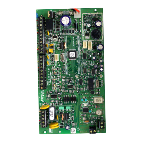
Avoid installing the 1759MG in the basement. Do not cut, bend or alter the antennae and ensure that electrical wires do not cross over the antennae as these may affect the signal reception. - Page 7 Figure 2: Spectra 1759MG Control Panel Overview “STATUS” LED: Flash once every second = normal ON 1 second and OFF 1 second = trouble “RX” LED: Always ON = panel is using phone line Flashes quickly when receiving signals Antennae Fast flash 4 seconds after power up = installer lock enabled from wireless devices.
-
Page 8: Auxiliary Power Terminals
The Spectra 1759MG control panel also has a 5A relay. This relay can be connected as shown in Figure 3 on page 5. The Alarm Relay can be programmed to follow the bell output or the activation and deactivation of the Global PGM (see Alarm Relay Options on page 35). -
Page 9: Single Zone Inputs
Detection devices such as motion detectors and door contacts are connected to the control panel's zone input terminals. Figure 4 demonstrates single zone input terminal connections recognized by Spectra. Once connected, the associated zone's parameters must be defined. For details refer to Zone Programming on page 12. -
Page 10: Keyswitch Connections
(Not using keypad zone) When a 1641 LCD keypad is connected to the 1759MG, the Keypad Zone Sending option (Option [2] key [1]) determines whether the status of the keypad zone will be transmitted to the control panel. The Keypad Zone Sending option of the 1641 keypad must be enabled during the following conditions: •... -
Page 11: Programming Methods
Decimal values from 000 to 255. Other sections will require that you enter Hexadecimal values from 0 to F. The required data will be clearly indicated in this manual as well as in the Spectra 1759MG Programming Guide. When entering the final digit in a section, the control panel will automatically save and advance to the next section. -
Page 12: Configuring The Led Keypad
EOL resistor. When key [2] is ON (illuminated), EOL is enabled and the keypad zone requires that an external EOL resistor be connected (refer to Spectra 1759MG Control Panel Overview on page 3 for more details). -
Page 13: Programming Using A Paradox Memory Key
Programming Using A Paradox Memory Key* Copy the sections of one Spectra control panel into the Paradox Memory Key (PMC-3). Then copy the contents of the Memory Key into as many Spectra control panels as needed. Each panel is programmed in less than 3 seconds. -
Page 14: Access Codes
Installer Code (Default: 0000 / 000000) The Installer Code is used to enter the 1759MG‘s programming mode (see page 7), which allows you to program all the features, options and commands of the control panel. The Installer Code can be 4- or 6-digits in length (see Access Code Length on page 10) where each digit can be any value from 0 to 9. -
Page 15: Lock Master Code
With this feature enabled, User Code 048 becomes a Duress Code. When forced to arm or disarm their system, users can enter a Duress Code (User Code 048) to arm or disarm the system which can immediately transmit a silent alert to the monitoring station, transmitting the duress report code programmed in section [196]. Spectra 1759MG... -
Page 16: Zone Programming
For example, 5 wireless transmitters and 3 hardwire inputs can be assigned to the expansion inputs. Spectra control panels cannot support more than eight expansion inputs. Refer to the appropriate module’s Instruction Sheet for details. -
Page 17: Reassign Zones To Expansion Inputs
See Table 4 on page 12 for the Zone Number Recognition. Only the control panel’s on-board inputs can be defined as a fire, delayed fire or a keyswitch zone. The on-board zones are zones 01 to 05. Figure 10: Spectra Zone Programming [001] = Zone 1 [009] = Zone 9... -
Page 18: Exclusive Zone Definitions
5.5.1 Entry Delay 1 Sections [001] to [015]: Zones 1 to 15, First Digit = 1 When the system is armed and a zone defined with Entry Delay 1 opens, the control panel will generate an alarm after the programmed Entry Delay 1 Timer elapses. This is to provide users with enough time to enter the protected area and disarm the system. -
Page 19: Programming A Wireless Fire Zone
Value 11) to a Fire report code (Prog. Value 04). If using Ademco Contact I.D., set the Contact ID Options from All Codes to Programmable (section [136] option [3] = OFF) and then enter the report code manually. See Spectra 1759MG Programming Guide for more information. Zone Partition Assignment... -
Page 20: Zone Options
Zone Options As demonstrated in Figure 10 on page 13, sections [001] to [015] represent zones 1 through 15 respectively. After entering the first two digits, select one or more of the following Zone Options by using the Multiple Feature Select Programming Method (see page 7): 5.9.1 Auto Zone Shutdown Sections [001] to [015] = Zones 1 to 15... -
Page 21: Zone Speed
If all detection devices connected to the control panel have input terminals that require 1KΩ end of line resistors, enable option [4] in section [132]. For details on using EOL resistors, refer to Single Zone Inputs on page 5. Spectra 1759MG... -
Page 22: Wireless Features
Part 6: Wireless Features The Spectra 1759MG allows for the addition of up to eight fully supervised Magellan wireless transmitters, and up to eight programmable remote controls. To program a wireless fire zone, refer to Programming a Wireless Fire Zone on page 15. -
Page 23: Viewing The Wireless Transmitter Signal Strength
Sections [631] to [638] Once wireless transmitters have been installed and assigned to the Spectra 1759MG, the signal strength of each transmitter can be verified in sections [631] to [638]. Each section represents the signal strength viewer for a specific device. For example, section [631] is the viewer for the device in section [601] and section [638] is the viewer for the device in section [608]. -
Page 24: Remote Control Programming
When the battery voltage of a wireless transmitter (motion detector or door contact) drops below a certain value, the Spectra 1759MG will send a low battery report code to the monitoring station, and a trouble will appear in the keypad’s trouble display. -
Page 25: Remote Control Button Programming
Remote Controls to User Access Codes on page 21). Sections [711] to [718] represent the remote controls assigned to sections [731] to [738] (refer to Assigning a Remote Control to the Spectra 1759MG on page 20). For example, the buttons for the remote control assigned in section [731] will be programmed in section [711]. -
Page 26: Arming And Disarming Options
[D] = Activates any PGMs that have Event Group #09* as their Activation Event * Event Group #07, #08 and #09 (Button Pressed on Remote) of the Spectra 1759MG PGM Table. For the PGM Table, please refer to the Spectra 1759MG Programming Guide (1759MG-EP). -
Page 27: Regular Arming Switches To Force Arming (Not To Be Used With Ul Installations)
Example: To arm partition 1 whenever there is no movement for a period of 4 hours, enable No Movement Auto-arming for partition 1 by turning on the [2] Option in section [133]. Then in section [075] enter 016 (16x15min = 240min = 4 hours). Spectra 1759MG... -
Page 28: Auto-Arming Options (Not To Be Used With Ul Installations)
7.7.1 No Movement Timer Section [075] = Partition 1, [076] = Partition 2 001 to 255 x15min, Default = Disabled Select the section corresponding to the desired partition and program the interval of time without movement you wish the control panel to wait before arming and/or sending the No Movement report code. If No Movement Auto-arming is disabled, the control panel can still send the No Movement report code when no movement has been detected for the period specified by the No Movement Timer. -
Page 29: No Exit Delay Beeps And No Bell Squawk When Stay Arming
In an armed system and a tamper wiring failure occurs on a zone, the control panel will follow the zone's Alarm Types setting (see page 16). In a disarmed system, it functions the same as Trouble Only setting, except it will also generate an audible alarm. Spectra 1759MG... -
Page 30: Keypad Panic Options
8.3.1 Tamper Bypass Options Section [132]: Zone Options Option [3] OFF = Will generate a tamper if detected on a bypassed zone (default) Option [3] ON = Tampers on bypassed zones will be ignored With option [3] on, the Tamper Recognition feature follows the zone bypass definition. This means the control panel will ignore any tampers detected on a bypassed zone. -
Page 31: Reporting And Dialer Settings
[6] = Pager DTMF (Tone) “Programmable” Option [3] - Section [136] The control panel [5] = Ademco Contact ID automatically generates all report codes. You do “Programmable” not have to program Option [3] - Section [136] any report codes. Spectra 1759MG... -
Page 32: Reporting/Dialer (Enable/Disable)
Reporting/Dialer (Enable/Disable) Section [135]: Dialer Options Option [3] OFF = Reporting/Dialer Disabled (default) Option [3] ON = Reporting/Dialer Enabled Report Codes A report code is a 1- or 2-digit hexadecimal value consisting of digits from 1 to F. Each section from [160] to [213] represents a set of up to four specific events and each of these events can be programmed with a separate 1- or 2-digit report code. - Page 33 Printer Fault: An error has occurred on the Printer Module. • Fail To Communicate: The control panel has failed all attempts to communicate with the monitoring station. The report code will be transmitted upon the next successful attempt. Spectra 1759MG...
-
Page 34: Monitoring Station Telephone Numbers
Section [151] = Phone#1, [152] = Phone#2, [153] = Backup Phone#: Up to 32 digits The 1759MG control panel can dial up to 2 different monitoring station telephone numbers. You can enter any digit from 0 to 9 and any special keys or functions (see Table 8) up to a maximum of 32 digits. For more information on how these telephone numbers are used, please refer to Event Call Direction on page 32 and Reporting Formats on page 30. -
Page 35: Reporting Formats
UL Note: The installer is required to verify the complete compatibility of the DAC Receiver and formats at least once per year. 9.5.1 Standard Pulse Formats The Spectra 1759MG can use the Ademco slow, Silent Knight and Sescoa standard pulse reporting formats (see Table 9 above). 9.5.2 Ademco Express The Ademco Express is a high-speed reporting format, which will transmit the 2-digit (11 to FF) report codes programmed into sections [160] to [213]. -
Page 36: Pager Delay
Pager Delay Section [083] 001 to 255 seconds, default = 5 seconds When using the Pager Reporting Format (see page 31), the control panel will wait for the Pager Delay period before transmitting the report codes. This is to allow time for the pager system to provide a dial tone or to bypass the “welcome” message before sending data. -
Page 37: Maximum Dialing Attempts
Example: The Closing Delinquency Timer for partition 1 in section [095] is programmed for 005 days. Spectra verifies when partition 1 was last disarmed at midnight every day. If partition 1 was not armed within the last 5 days, Spectra will transmit a Closing Delinquency event to the monitoring station. -
Page 38: Zone Restore Report Options
With option [6] OFF, the 1759MG will send the Zone Alarm Restore report codes (see page 29) to the monitoring station when the zone has returned to normal and the Bell Cut-Off Timer has elapsed (see page 25). With option [6] ON, the 1759MG will send the Zone Alarm Restore report codes to the monitoring station as soon as the zone returns to normal or when the system is disarmed. -
Page 39: Pgm Deactivation Event
Instead of deactivating the PGM when a specific event occurs, the PGM can deactivate after a programmed period elapses (see PGM Delay below). For the Event List see the PGM Table in the Spectra 1759MG Programming Guide. If using the PGM Delay, these sections can be used as a second activation event. -
Page 40: System Settings
= Partitioning Enabled The 1759MG is equipped with a partitioning feature which can divide the alarm system into two distinct areas identified as Partition 1 and Partition 2. Partitioning can be used in installations where shared security systems are more practical, such as an office/warehouse building. -
Page 41: Keypad Tamper Supervision
[1]. Option [2] regulates whether the keypads will be activated at the touch of a key or only when an access code is entered. Option [3] determines the amount of time without action before the system enters Confidential Mode (5 seconds or 2 minutes). Spectra 1759MG... -
Page 42: Installer Quick Functions Keys
By enabling this option, the control panel will supervise the 4- or 8-Zone Expansion Bus Module (SPC/APR3-ZX4 or SPC/APR3- ZX8) connected to the Spectra bus. This means that whenever the Zone Expansion Bus Module is disconnected or is not communicating with the control panel, the control panel will attempt to transmit the Module Fault report code programmed in section [210] and the Module Loss Failure will appear in the keypad’s trouble display (see page 42). -
Page 43: Wireless Transmitter Low Battery Supervision
Memory Key (refer to Programming Using A Paradox Memory Key* on page 9), you can reprogram the modules with the settings saved in the control panel. To do so, enter section [750] and press [ ]. The keypad will emit 2 beeps every second while ENTER downloading. Spectra 1759MG... -
Page 44: Settings For Winload Software
This 4-digit password identifies the PC to the panel before establishing communication. Program the same PC Password into both the Spectra control panel and the WinLoad software. If the passwords do not match, the WinLoad software will not establish communication. -
Page 45: Answer Winload Software
WinLoad software automatically goes into Wait for Call mode, ready to answer when the control panel calls back. Please note that the PC Telephone Number must be programmed in section [150] in order to use the Call Back feature. Spectra 1759MG... -
Page 46: User Operation
13.1 Trouble Display The Spectra system continuously monitors fourteen possible trouble conditions. When a trouble condition occurs, the [ ] key or ] indicator will illuminate on the LED keypads or “Trouble” will appear on the LCD keypad’s screen. Press the [... -
Page 47: Programming Access Codes
Access codes are personal identification numbers that allow you to enter certain programming modes, arm or disarm your system as well as activate or deactivate PGMs. The Spectra security system supports the following: System Master Code arms or disarm partitions using any arming method and can create, modify or delete any user access code. -
Page 48: Regular Arming
13.4 Regular Arming This method, commonly used for day-to-day arming, will arm all the zones in the selected partition. If you make a mistake, the keypad will emit a rejection beep. When you have correctly armed the system, the appropriate indication will turn on and the exit delay will be initiated. -
Page 49: One-Touch Arming
13.11 Panic Alarms In case of emergency, the Spectra system provides up to three panic alarms. These panic alarms, if programmed, will immediately generate an alarm after pressing and holding two specific keys for two seconds, as described below. Press and hold keys [1] and [3] for a panic alarm. -
Page 50: Alarm Memory Display
Code 2. Please note that the control panel will enter a 60-second exit delay period before arming the system. At this point, Auto- arming can be cancelled by entering a valid access code. 13.13 Alarm Memory Display A record of all alarm situations that occur will be stored in memory. After disarming the system, pressing the [ ] key will display which zones were in alarm during the alarm period. -
Page 51: Fcc Warnings
Class B digital devices, pursuant to Part 15 of FCC rules. These limits are pipe system, if present, are connected together. This precaution may be designed to provide reasonable protection against harmful interference in a particularly important in rural areas. residential installation. This equipment generates, uses and can radiate Spectra Series... - Page 52 Canadian and international patents may also apply. L'indice de charge (IC) assigné à chaque dispositif indique, pour éviter Spectra, WinLoad, InTouch and Digiplex are trademarks or toute surcharge, le pourcentage de la charge totale qui peut être raccordée registered trademarks of Paradox Security Systems Ltd. or its à...
-
Page 53: Index
Beep On Exit Delay ............24 Dialing Attempts ...............33 Beep On Trouble .............37 Dialing Method ..............32 Bell Cut-Off Timer ............25 Disarm Reporting Options ..........33 Bell on Communication Failure ........32 Disarming .................43 Bell Output Duress Code ..............11 ..............4 Connection Duress Report Code ............29 Spectra Series... - Page 54 ............5 Zone Connection Keyswitch Emergency Panic Report Code ........29 ................ 45 Arming Entry Delay ..............14 ............ 28 Arming, Report Code EOL Zones ..............17 ..............6 Connections Event Buffer Transmission ..........41 ..........28 Disarming Report Code Event Call Direction ............
- Page 55 Switch to Stay Arming ............22 .............30 Tx Supervision Loss System ..........30 Tx Supervision Restore ..............10 Master Code Report Code, Special Alarm ............36 Real-Time Clock ............29 Auto Zone Shutdown ...............36 Settings .............29 Auxiliary Panic ..........29 Trouble Report Codes ................29 Duress Spectra Series...
- Page 56 ..........30 ............... 14 Trouble Restore Codes Entry Delay 2 ............... 14 Follow Zones .............. 14 Instant Zones Zone Options Tamper Bypass Options ..........26 ..............16 Alarm Types Tamper Recognition ............25 ............ 16 Auto Zone Shutdown Telephone Line Connection ..........4 ....
- Page 57 Notes...
- Page 60 8:00 a.m. to 8:00 p.m. EST. For technical support outside Canada and the U.S. call 00-1-450-491-7444, Monday to Friday from 8:00 a.m. to 8:00 p.m. EST. Please feel free to visit our website at www.paradox.ca. 780 Industriel Blvd., Saint-Eustache (Quebec) J7R 5V3 CANADA Tel.: (450) 491-7444 Fax: (450) 491-2313 www.paradox.ca 09/2004 1759MG-EI05 PRINTED IN CANADA...
Need help?
Do you have a question about the 1759MG and is the answer not in the manual?
Questions and answers