
Related Manuals for Spectra 1725


Summary of Contents for Spectra 1725
- Page 1 & I EFERENCE NSTALLATION ANUAL V1.2 PECTRA ONTROL ANELS 1725, 1725EX, 1728 1728EX 1758 1758EX...
-
Page 3: Table Of Contents
TABLE OF CONTENTS INTRODUCTION ............................4 Features ..................................4 Specifications ................................4 Detectors, Keypads and Expansion Modules ....................... 5 INSTALLATION ............................7 Location and Mounting ..............................7 Earth Ground ................................8 AC Power ..................................8 Back up Battery ................................9 Auxiliary Power Terminals ............................9 Telephone Line Connection ............................ - Page 4 No Exit Delay When Arming with Remote Control ..................... 28 No Exit Delay Beeps and No Bell Squawk When Stay Arming .................. 28 ALARM OPTIONS ..........................29 Bell Cut-Off Timer ............................... 29 Recycle Alarm ................................29 Tamper Recognition ..............................29 Keypad Panic Options ..............................30 REPORTING AND DIALER SETTINGS ....................31 Reporting/Dialer (Enable/Disable) ..........................
- Page 5 Call WinLoad Software ...............................45 Answer WinLoad Software ............................46 Auto Event Buffer Transmission ..........................46 Call Back Feature ...............................46 LIBERATOR MODULE .......................... 47 Wireless Transmitter Assignment (Liberator) ......................47 Supervision Options (Liberator) ..........................47 On-Board Tamper Recognition (Liberator) .........................48 PGM Activation event (Liberator) ..........................48 PGM De-Activation Event (Liberator) .........................48 PGM Delay (Liberator) ..............................48 PGM Follows Global PGM (Liberator) ........................49...
-
Page 6: Introduction
• Simple, direct and logical programming • Event Call Direction: The Spectra Series Control Panel events are divided into 5 groups of events. Each of these event groups can be programmed with a separate dialing sequence. • Two 32-digit Central Station Telephone Numbers and one 32-digit Back-up Telephone Number •... -
Page 7: Detectors, Keypads And Expansion Modules
“key-light” feature, provides a user-friendly display of the system’s current status. For example, if zone 5 is open, the [5] key turns on. What could be simpler? Designed to be compatible with any Spectra Series control panel, our Euro- Style Spectra keypads eliminate stocking and ordering concerns. - Page 8 SPC-319 W IBERATOR IRELESS ODULE Connected to the Spectra control panel’s communication bus, the fully supervised Liberator Wireless Bus Module (SPC-319) allows you to add up to eight fully programmable remote controls and up to eight Liberator Wireless Detectors and Contact Switches (door contacts).
-
Page 9: Installation
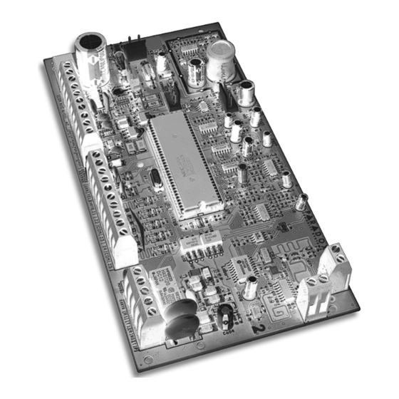
Select an installation site that isn't easily accessible to intruders and leave at least 2" around the panel box to permit adequate ventilation and heat dissipation. The installation site should be dry and close to an AC source, ground connection and telephone line connection. Figure 2-1A: Spectra 1725, 1725EX, 1728 and 1728EX Control Panel Overview PECTRA ERIES... -
Page 10: Earth Ground
Figure 2-1B: Spectra 1758 and 1758EX Control Panel Overview Other than the location of the parts on the board and the items that have been indicated below, connections to these control panels are identical to those on page 7. EARTH GROUND Connect the zone and dialer ground terminals from the control panel to the cabinet and cold water pipe or grounding rod as per local electrical codes. -
Page 11: Back Up Battery
The bell output supplies 12VDC upon alarm and can support two 20-watt sirens or one 30-watt siren. The bell output uses a fuseless circuit and will automatically shut down if the current exceeds 3A (1725, 1725EX, 1728, and 1728EX) or 2.5A (1758, and 1758EX). When this occurs the “Maximum Bell Current” failure will appear in the keypads’... -
Page 12: Programmable Output Connections
ALARM RELAY The Spectra 1758 and 1758EX control panels have an optional 5A relay. This relay can be connected as shown in Figure 2-1B on page 8. Please note that the Alarm Relay can be programmed to follow the bell output or the activation and de-activation of the Global PGM (see Alarm Relay Options on page 40). -
Page 13: Single Zone Inputs
Detection devices such as motion detectors and door contacts are connected to the control panel's zone input terminals labeled between 1 and 5 depending on the Spectra control panel being used. Figure 2-5 demonstrates single zone input terminal connections recognized by the Spectra Series control panels. Once connected, the associated zone's parameters must be defined. -
Page 14: Double Zone Inputs (With Atz Option Only)
2.14 DOUBLE ZONE INPUTS (WITH ATZ OPTION ONLY) Enabling the ATZ feature (see page 25) allows you to install two detection devices per input terminal. The ATZ feature is a software-oriented feature. Therefore, there is no need for extra modules, simply connect the devices as shown in Figure 2-6. -
Page 15: Connecting A Liberator Spc-319 Wireless Module
-” of the control panel. The Liberator Module does not function with the Spectra 1758 and 1758EX. Do not cut, bend, or alter the antennas. Avoid mounting the Receiver Module near or on metal as this may affect its sensitivity. - Page 16 Figure 2-9: Zone Expansion Module (ZX8) 2.17.1 Z (SPC-ZX4/ZX8) ONNECTIONS Each input terminal, allows you to connect one detection device. These devices are connected exactly as shown in Figure 2-5 on page 11. Devices connected to the Zone Expansion Module's input terminals must be enabled as described in Zone Input Assignment on page 50 and the its parameters must be defined as explained in Zone Programming on page 20.
-
Page 17: Programming Methods
Decimal values from 000 to 255. Other sections will require that you enter Hexadecimal values from 0 to F. The required data will be clearly indicated in this manual as well as in the Spectra Series Programming Guide. -
Page 18: Programming Using A Paradox Memory Key
Memory Key into as many control panels as you need. Each control panel is programmed in less than 3 seconds. If used with a Spectra 1758/EX, you will have to reassign the remote controls (see page 53). Download to DESTINATION Control Panel 1) Remove AC and battery power from the control panel. -
Page 19: Access Codes
PART 4: ACCESS CODES The Spectra Series control panels support the following 48 access codes: INSTALLER CODE: Used to program all control panel settings except User Access Codes. SYSTEM MASTER CODE (001) Provides full access. Arm and disarm using any method described in the User Code Options on page 17 as well as program the User Access Codes. - Page 20 4.4.1 ARTITION SSIGNMENT Sections [302] to [348] = User Codes 002 - 048 Option [1] OFF = Deny access to partition 1 Option [1] ON = User code has access to partition 1 (default) If Partitioned (see page 41), user codes with this option enabled can arm and disarm partition 1. If the system is not partitioned, you must assign partition 1 to the User Access Code.
-
Page 21: Lock Master Code
LOCK MASTER CODE Section [127] = System Options Option [4] OFF = Lock System Master Code Disabled (default) Option [4] ON = Lock System Master Code Enabled With this feature enabled, the control panel will lock the System Master Code (001). This means that pressing the System Master Code cannot be deleted but it can be changed. -
Page 22: Zone Programming
Zone 15 Zone 15 Note: In the 1725EX zone 5 does not exist. In the 1725 zones 5 and 10 do not exist. What is an Expansion Input? There are a total of eight expansion inputs available. Each hardwired input on a Zone Expansion Module or wireless transmitter used by the Liberator Wireless Bus Module can be assigned to an expansion input. -
Page 23: Zone Definitions
Figure 5-1: Spectra Zone Programming [001] = Zone 1 [009] = Zone 90 Press the [002] = Zone 2 [010] = Zone 10 ] key ENTER [003] = Zone 3 [011] = Zone 11 [004] = Zone 4 [012] = Zone 12... - Page 24 5.1.3 OLLOW ONES Sections [001] - [016] = Zones 1 - 16: First Digit = 3 When an armed Follow Zone opens, the control panel will immediately generate an alarm, unless an Entry Delay zone opens first: • If an armed Follow Zone opens after an Entry Delay zone opens, the control panel waits until the Entry Delay Timer has elapsed before generating an alarm.
-
Page 25: Zone Partition Assignment
5.1.6 UZZER ELAYED Sections [001] - [016] = Zones 1 - 16: First Digit = 6 Whenever a 24Hr. Buzzer Zone opens, whether the zone is armed or disarmed, the control panel sets off the keypads’ buzzers to indicate the zone was breached. The control panel will report the alarm but will not enable the bell/siren output. - Page 26 5.3.4 LARM YPES Sections [001] - [016] = Zones 1 - 16 [4] OFF / [5] OFF - Audible Steady (default) When the conditions for an alarm have been met, the control panel can transmit the appropriate Zone Alarm report code (see page 33) and provides a steady output for any bells or sirens connected to the control panel’s output.
-
Page 27: Zone Speed
Section [002] - If zone 2 is set as a 24Hr. Burglary Zone Option [1] OFF = Maintained (default) Option [1] ON = Momentary To arm the system using the Maintained Keyswitch, set the switch or button to the "on" position. To disarm the system set the keyswitch to the "off"... -
Page 28: Arming And Disarming Options
PART 6: ARMING AND DISARMING OPTIONS SWITCH TO STAY ARMING Section [133] = Partition 1, [134] = Partition 2 Option [7] OFF = Switch to Stay Arming Disabled (default) Option [7] ON = Switch to Stay Arming Enabled If a user Regular arms a partition but does not exit through (open and close) an Entry Delay zone during the Exit Delay, the control panel can be programmed to switch from Regular Arming to Stay Arming. -
Page 29: No Movement Auto-Arming
6:30PM = 18:00) you wish the control panel to attempt to arm the selected partition and/or send the Late to Close report code. If Timed Auto-Arming is disabled, the control panel will still send the Late to Close report code at the time specified by the Auto-Arm Timer. NO MOVEMENT AUTO-ARMING Section [133] = Partition 1, [134] = Partition 2 Option [2] OFF = No Movement Auto-Arming Disabled (default) -
Page 30: Bell Squawk On Arm/Disarm With Keypad
6.10 BELL SQUAWK ON ARM/DISARM WITH KEYPAD Section [130] - Arming/Disarming Options Option [7] OFF = Bell Squawk on Arm/Disarm Disabled (default) Option [7] ON = Bell Squawk on Arm/Disarm Enabled When this feature is enabled, the bell or siren will "squawk" once upon arming and twice upon disarming. 6.11 BELL SQUAWK ON ARM/DISARM WITH REMOTE CONTROL Section [131] - Arming/Disarming Options Option [3] OFF = Bell Squawk on Arm/Disarm with Remote Control Disabled (default) -
Page 31: Alarm Options
PART 7: ALARM OPTIONS BELL CUT-OFF TIMER Section [073] = Partition 1, [074] = Partition 2: 000 = Disabled, 001-255 minutes, Default = 4 min. After an audible alarm, the bell or siren will stop upon disarming of the partition or when the Bell Cut-Off Timer has elapsed, whichever comes first. -
Page 32: Keypad Panic Options
KEYPAD PANIC OPTIONS Section [128] - General Options Option [1] OFF = Emergency Panic Disabled (default) Option [1] ON = Emergency Panic Enabled Pressing the [1] & [3] keys simultaneously on the keypad for 2 seconds will generate a silent or audible alarm as defined by option [4]. -
Page 33: Reporting And Dialer Settings
PART 8: REPORTING AND DIALER SETTINGS The following section explains all the features and options that must be programmed in order for your security system to properly report system events to a central station. When an event (e.g. zone in alarm) occurs in the system, the control panel verifies if a report code was programmed in the section corresponding to the event (except Ademco Contact ID “All Codes”). -
Page 34: Reporting/Dialer (Enable/Disable)
REPORTING/DIALER (ENABLE/DISABLE) Section [135] - Dialer Options Option [3] OFF = Reporting/Dialer Disabled (default) Option [3] ON = Reporting/Dialer Enabled REPORT CODES A report code is a 1 or 2-digit hexadecimal value, consisting of digits from 1 to F. Each section from [160] to [213] represents a set of up to four specific events and each of these events can be programmed with a separate 1 or 2- digit report code. - Page 35 8.2.4 PECIAL ISARMING EPORT ODES Section [186] Whenever using one of the special disarming features, the control can send the report code to the central station, identifying how the system was disarmed. __/__ : A partition is disarmed during the Timed Auto-Arm's 60-second exit delay (see CANCEL AUTO page 26).
-
Page 36: Central Station Telephone Numbers
Section [151] = Phone#1, [152] = Phone#2, [153] = Back-up Phone#: Up to 32 digits The Spectra Control Panels can dial up to 2 different central station telephone numbers. You can enter any digit from 0 to 9 and any special keys or functions (see Table 5 on the next page) up to a maximum of 32 digits. For more information on how these telephone numbers are used, please refer to Event Call Direction on page 36 &... -
Page 37: Partition Account Numbers
Section [140]: 1st digit = Format for Phone #1, 2nd digit = Format for Phone # The Spectra Control Panels can use a number of different reporting formats and each Central Station Telephone Number can be programmed with a different reporting format. The first digit entered into section [140] represents the reporting format used to communicate with Central Station Telephone Number 1, the second digit represents the reporting format used to communicate with Central Station Telephone Number 2. -
Page 38: Event Call Direction
Contact ID Report Codes for every event in sections [160] to [213]. Refer to the “All Codes” Ademco Contact ID Report Code List in the Spectra Programming Guide. When using the Ademco Contact ID Programmable format, both telephone numbers must use this reporting format. -
Page 39: Bell On Communication Failure
BELL ON COMMUNICATION FAILURE Section [135] - Dialer Options Option [6] OFF = Bell On Communication Failure Disabled (default) Option [6] ON = Bell On Communication Failure Enabled If the control panel fails to communicate with the central station when the system is armed, it will enable the BELL output, setting off any bells or sirens connected to the output. -
Page 40: Disarm Reporting Options
8.17 DISARM REPORTING OPTIONS Section [131] - Arming /Disarming Options Option [1] OFF = Always Report Disarming Option [1] ON = Report Disarming Only After Alarm (default) With option [1] off, the control panel will send the Disarming report codes (see page 32) to the central station every time the system is disarmed. -
Page 41: Programmable Outputs
1. Enter section that represents the desired PGM. PGM1 = [120], PGM2 = [122], Global PGM = [124] 2. Enter the Event Group # (refer to the PGM table in the Spectra Programming Guide). 3. Enter the Sub-Group # (refer to the PGM table in the Spectra Programming Guide). -
Page 42: Pgm Delay
Section [127] = PGM1, [129] = PGM2, [131] = Global PGM These three options have been added to this new version of the Spectra control panels allowing you to specify the PGMs as normally open (N.O.) or normally closed (N.C.). Any PGM in the Spectra system that has been programmed to follow the Global PGM will also follow the Global PGM type defined by this option. -
Page 43: System Settings
PART 10: SYSTEM SETTINGS 10.1 HARDWARE RESET Performing a hardware reset will set all control panel settings to factory default except for the Panel ID and PC Password. Also, the event buffer will not be erased. To perform a power down reset: 1. -
Page 44: Keypad Tamper Supervision
Zone Tamper report code as originating from partition 1. A Tamper/ Zone Wiring Failure will also appear in the keypads’ Trouble Display (see page 54). Table 7: Zone Tamper Report Code for Keypad Tamper Supervision Failure 1725EX 1725 1728EX 1728 Keypad Tamper... -
Page 45: Zone Expansion Module Supervision
By enabling this option, the control panel will supervise the Zone Expansion Module (SPC-ZX4 or ZX8) connected to the Spectra bus. This means that whenever the Zone Expansion Module is disconnected or isn’t communicating with the control panel, the control panel will attempt to transmit the Module Fault report code programmed in section [210] and the Module Loss Failure will appear in the keypads’... -
Page 46: Reprogram All Expansion Modules
Only" setting, except it will also generate an audible alarm. In an armed system, the control panel will follow the zone's Alarm Types setting (see page 24). Functions only with the 1725, 1725EX, 1728 and 1728EX control panels. 10.13.1 R... -
Page 47: Settings For Winload Software
Panel Identifier in the WinLoad software is the same. If the codes do not match, the control panel will not establish communication. Therefore, be sure to program the same panel identifier into both the Spectra control panel and the WinLoad software. -
Page 48: Answer Winload Software
11.6 ANSWER WINLOAD SOFTWARE ] + [ ] + [ ENTER INSTALLER CODE FORCE In order to perform on-site upload/download connect your computer directly to the control panel using an ADP-1 line adapter. In the WinLoad software set "Dialing Method" to "Blind Dial". Program the panel telephone number in WinLoad software and follow the instructions on the ADP-1 adapter. -
Page 49: Liberator Module
[601] to [608] represents Expansion Inputs 1 through 8 respectively. Each Expansion Input represents a specific zone in the system depending on the type of Spectra control panel being used and whether the ATZ option is enabled. Once the transmitters have been assigned, their associated zones must be programmed as described in Zone Programming on page 20. -
Page 50: On-Board Tamper Recognition (Liberator)
[615]. Please note that the corresponding zone must be programmed (see page 20). Example: If you program 003 (Expansion Input 3) in section [615] of a Spectra 1725 panel and the ATZ feature is enabled, when a tamper occurs on the Liberator module, the control panel will transmit the Zone Tamper report code as originating from zone 15. -
Page 51: Pgm Follows Global Pgm (Liberator)
Section [630] This feature will display the serial number of any Liberator Motion Detector, Contact Switch or Remote Control on any Spectra keypad. To do so: 1. Enter section [630] 2. If it is a Liberator Motion Detector or Contact Switch, press its tamper switch. If it is a Liberator Remote Control, press any two buttons on the remote control. -
Page 52: Zone Expansion Module
PART 13: ZONE EXPANSION MODULE The following options and features are only available to program when a Zone Expansion Bus Module has been connected to the Spectra control panel’s communication bus as shown on page 13. The Zone Expansion Modules provide you with up to 4 (SPC-ZX4) or up to eight (ZX8) additional hardwired inputs and one normally open 50mA PGM output (ZX8 only). -
Page 53: Pgm Activation Event (Zone Module)
1. Enter section [656] 2. Enter the Event Group # (refer to the Zone Module PGM table in the Spectra Programming Guide). If you program the “Follows Global PGM” event group, it will follow the event programmed in section [124] 3. -
Page 54: Remote Control Programming
PART 14: REMOTE CONTROL PROGRAMMING When using the Liberator Wireless Bus Module with a 1725, 1725EX, 1728 or 1728EX control panel or when using the Spectra 1758 or 1758EX control panel with wireless capability built-in, you can program up to 8 remote controls as shown in the following sections. -
Page 55: Remote Control Assignment (Liberator Only)
Table 8: Button Programming Sections Button or Button Combination [711] - [718] 1st Digit = Button A 2nd Digit = Button B 3rd Digit = Button C 4th Digit = Button D 5th Digit = Buttons A & B pressed simultaneously 6th Digit = Buttons C &... -
Page 56: User Operation
PART 15: USER OPERATION 15.1 TROUBLE DISPLAY The Spectra system continuously monitors fourteen possible trouble conditions. When a trouble condition occurs, the ] button or [ ] indicator will illuminate on the LED keypads or “Trouble” will appear on the LCD keypad’s screen. -
Page 57: Partitioning
15.2 PARTITIONING The Spectra system is equipped with a partitioning feature which can divide the alarm system into two distinct areas identified as Partition 1 and Partition 2. Partitioning can be used in installations where shared security systems are more practical, such as a home office or warehouse building. If the system is not partitioned, all User Codes and features will be recognized as belonging to partition 1. -
Page 58: Regular Arming
How Do I Disarm the System or Deactivate an Alarm? 1) Key in your ACCESS CODE The arm or alarm indication will turn off and the keypad will emit a “ ”. CONFIRMATION BEEP IF YOU HAVE ACCESS TO BOTH PARTITIONS: 2) Press the button corresponding to the partition you wish to Disarm or to Disarm both partitions, press the [1] key then after the confirmation beep press the [2] key. -
Page 59: Force Arming
15.8 FORCE ARMING Force Arming allows users to rapidly arm the system, without having to wait for all zones in the system to be closed. Force Arming is commonly used when a motion detector is protecting the area occupied by a keypad. Therefore, when arming the system, if the motion detector is set as a Force Zone, the control panel will ignore the zone and allow users to arm the system even if the zone is open. -
Page 60: Keyswitch Arming
"on" position then turn it back to the "off" position. Repeating this sequence will disarm the system. 15.12 PANIC ALARMS In case of emergency, the Spectra system provides up to three panic alarms. These panic alarms, if programmed, will immediately generate an alarm after pressing and holding two specific buttons for two seconds, as described below. -
Page 61: Programming Chime Zones
15.15 PROGRAMMING CHIME ZONES This feature allows users to program which zones will be "Chime Enabled". A "Chime Enabled" zone will cause the keypad to emit a rapid intermittent beep tone ( ) advising the user every time it is opened. Each keypad must BEEP BEEP BEEP... - Page 62 UL WARNING All outputs are Class 2 or power-limited, except for the battery terminal.The Class 2 and power-limited fire alarm circuits shall be installed using CL3, CL3R, CL3P, or substitute cable permitted by the National Electrical Code, ANSI/NFPA 70. FCC WARNINGS IMPORTANT INFORMATION This equipment complies with Part 68 of the FCC rules subpart D and CS-03.
- Page 63 ATTACHMENT LIMITATION NOTICE The Industry Canada label identifies certified equipment. This certification means that the equipment meets certain telecommunications network protective, operational and safety requirements. The Department does not guarantee the equipment will operate to the user's satisfaction. Before installing this equipment, users should ensure that it is permissible to be connected to the facilities of the local telecommunications company. The equipment must also be installed using an acceptable method of connection.
-
Page 64: Index
INDEX Numerics 24Hr. Buzzer Zone Call Back Feature 24Hr. Delayed Fire Zone Call Upload/Download Software 24Hr. Standard Fire Zone Call WinLoad Software Cancel Communication Central Station Telephone Numbers Charge Current AC Power Chime Zones Access Code Length Clock Access Code Programming Clock Adjust Access Codes Connecting... - Page 65 Feature Select Programming Method No Arming On Battery Fail Fire Circuits No Arming on Supervision Loss Fire Zone, Delayed No Arming On Tamper Trouble Fire Zone, Standard 24 Hr. No Audible Feedback Upon Stay Arming Follow Zones No Exit Delay When Arming with Remote Control Force Arming No Movement Auto-Arming Force Zones...
- Page 66 System Master Code System Real-Time Clock Quick Arming System Settings Quick Functions Keys (Installer) System Trouble Report Codes System Trouble Restore Codes Real-Time Clock Recall Bypass Tamper Bypass Options Recent Close Delay Tamper Recognition Recycle Alarm Tamper Recognition (Liberator) Regular Arming Tamper Recognition (Zone Module) Regular Arming Switches to Force Arming Telephone Line Connection...
- Page 67 Printed in Canada 02/01 SPECEI-07...
Need help?
Do you have a question about the 1725 and is the answer not in the manual?
Questions and answers