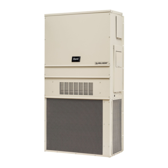
Table of Contents
Advertisement
INSTALLATION INSTRUCTIONS
WALL MOUNTED PACKAGED
W17A2-A
W36A2-A
W18A2-A
W36A2-B
W24A2-A
W36A2-C
W24A2-B
W36A2-D
W24A2-C
W36A2-E
W24A2-D
W36A2-F
W24A2-F
W42A2-A
W30A2-A
W42A2-B
W30A2-B
W42A2-C
W30A2-C
W42A2-E
W30A2-D
W42A2-F
W30A2-F
AIR CONDITIONER
Models:
W48A2-A
W48A2-B
W48A2-C
W48A2-E
W48A2-F
W60A2-A
W60A2-B
W60A2-C
W60A2-E
W60A2-F
W70A2-A
W70A2-B
W70A2-C
W70A2-F
Bard Manufacturing Company, Inc.
Bryan, Ohio 43506
www.bardhvac.com
W17L2-A
W42L2-A
W18L2-A
W42L2-B
W24L2-A
W42L2-C
W24L2-B
W42L2-F
W24L2-F
W48L2-A
W30L2-A
W48L2-B
W30L2-B
W48L2-C
W30L2-C
W48L2-F
W36L2-A
W60L2-A
W36L2-B
W60L2-B
W36L2-C
W60L2-C
W36L2-F
W60L2-F
W70L2-A
W70L2-B
W70L2-C
W70L2-F
Manual:
Supersedes: 2100-581C
Date:
W30A2DA
W30A2DB
W30A2DC
W36A2DA
W36A2DB
W36A2DC
W42A2DA
W42A2DB
W42A2DC
W48A2DA
W48A2DB
W48A2DC
W60A2DA
W60A2DB
W60A2DC
2100-581D
7-21-16
Page
1 of 26
Advertisement
Table of Contents

Summarization of Contents
Wall Mount General Information
Model Nomenclature
Explains the alphanumeric model naming convention for wall-mounted AC units.
Shipping Damage
Procedures for checking and reporting shipping damage upon equipment receipt.
General Unit Information
General notes about installation, safety, and unit capabilities.
Start Up Procedures
Safety Practices
Crucial safety guidelines for handling R-410A refrigerant and Polyol Ester oil during unit operation.
Compressor Control Module Operation
Delay-on-Make and Delay-on-Break Timer
Details on the timer function for compressor start-up and shutdown sequences.
High Pressure Switch and Lockout Sequence
How the high pressure switch triggers lockout and its reset procedure.
Low Pressure Switch, Bypass and Lockout Sequence
Explains low pressure switch operation, lockout, and reset for compressor protection.
Alarm Relay Output
Function of the alarm terminal for indicating lockout conditions.
Control Module Adjustments
Potentiometer settings for delay-on-break timing and typical dual unit settings.
Service Procedures
Fan Blade Setting Dimensions
Correct fan blade setting for optimal air delivery across the outdoor coil.
R-410A Refrigerant Charge
Factory refrigerant charge and using pressure tables for evaluation.
Removal of Fan Shroud
Step-by-step instructions for removing and reinstalling the fan shroud assembly.


Need help?
Do you have a question about the W24A2-A and is the answer not in the manual?
Questions and answers