Bard WA Series Installation Instructions Manual
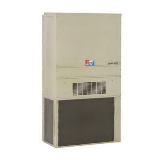
Wall mount air conditioner
Hide thumbs
Also See for WA Series:
- User manual (87 pages) ,
- Installation instructions manual (57 pages) ,
- Literature assembly (128 pages)
Chapters
Table of Contents
Troubleshooting

Related Manuals for Bard WA Series


Summary of Contents for Bard WA Series
- Page 1 Literature Assembly 911-0764 Contains the following: 2100-034(F) Users Guide 2100-479 Leak Test Evacuation Charging 2100-689 Wall Mount PKG A/C Manual 2110-1449(A) Replacement Parts Manual 7960-810 Supplemental 50HZ Instructions 7960-420 Warranty...
- Page 3 USER’S GUIDE For all Packaged Systems (Air Conditioners and Heat Pumps) WA & WL - Series Air Conditioners IH - Series Air Source Heat Pumps WH & SH - Series Air Source Heat Pumps PA - Series Air Conditioners PH - Series Air Source Heat Pumps QA - Series Air Conditioners QH - Series Air Source Heat Pumps MANUAL 2100-034 REV.
- Page 4 TABLE OF CONTENTS General Information Air Filters Page 3 Outdoor Coil Page 3-4 Routine Equipment Outdoor Maintenance Page 4 Basic Operating Principles Air Conditioners Page 4-5 Heat Pump (Air-to-Air) Page 5-6 Heat Pump (Water-to-Air) Page 6 Ventilation Page 7 Dehumidification Circuits Page 7 Automatic Control Systems Thermostats...
- Page 5 This manual is generic in nature and covers a wide range of heating and cooling products manufactured by Bard Manufacturing Company. It is intended to be a general guide for care and operation of typical systems and covers the most important features you should be aware of and are responsible for as the user of the equipment.
- Page 6 Depending on the specific equipment involved, the surface that can accumulate debris can be on the opposite side that is exposed to view when standing in front of the machine. Closely review the machine when operating to see which direction or path that the airflow moves through the machine, and if the air inlet side of the coil is hidden, try to observe the back (hidden) side by looking into the side grilles, using flashlight if necessary.
- Page 7 stream in the process. It may take several hours to pull down a hot, moist building or structure on initial startup, or anytime the system has been turned off for a long period of time. It is generally best to set the thermostat at a comfortable temperature and let it control the system as needed, rather than turning it on and off.
- Page 8 The length of the defrost cycle will vary depending upon actual outdoor temperature, humidity levels and amount of accumulated frost. It could range from 1-2 minutes up to but not exceeding 10 minutes. When the defrost cycle terminates, the reversing valve will shift back to heating mode and the outdoor fan will restart.
- Page 9 User’s Guide. Many installers also install thermostats other than those offered by Bard, and must determine proper compatibility prior to installation.
- Page 10 50 and 60% Relative Humidity (RH) and typically affords acceptable human comfort conditions for most individuals, and under no circumstances should be set lower than 40% as overcooling of the conditioned space and/or freeze-ups of the indoor coil may occur. INSUFFICIENT COOLING OR HEATING In extremely hot or cold weather your system will continue to deliver its normal supply of conditioned air.
- Page 11 HELPFUL HINTS AND GOOD OPERATING PRACTICES The following information will help you enjoy the full comfort and benefits of your Bard cooling and heating system, maximize the performance and efficiency, and help extend the life of your system: 1. Always keep the equipment in peak operating condition with routine scheduled maintenance, especially for the air filters and to assure clean outdoor coil.
- Page 13 SERVICING PROCEDURE R-410A LEAK TEST EVACUATION CHARGING Bard Manufacturing Company, Inc. Manual No.: 2100-479 Supersedes: NEW Bryan, Ohio 43506 File: Volume I, Tab 1 Since 1914...Moving ahead, just as planned. Date: 03-08-07 Manual 2100-479 Page 1 of 11...
-
Page 14: Table Of Contents
CONTENTS General Troubleshooting the Mechanical System Recovery Equipment Rated for R-410A ....3 Air Conditioning & Heat Pump - Cooling .....9 Leak Detectors ............3 Gauge Manifold ............3 Low Suction — Low Head Pressure ......9 High Suction — Low Head Pressure ......9 Attaching Gauge Manifold ........3 Low Suction —... -
Page 15: General
GENERAL GAUGE MANIFOLD WARNING WARNING The oils used with R-410A refrigerant are hydroscopic and absorb water from the Gauge manifold must be suitable for use atmosphere readily. Do not leave systems with R-410A refrigerant and POE oils. open to the atmosphere for more than 5 minutes. -
Page 16: Attaching Manifold Hose To Schrader Valve
ATTACHING MANIFOLD HOSE TO 3. Close drum valve and disconnect from center port. Release nitrogen or CO2 into the atmosphere through SCHRADER VALVE suction line of gauge manifold. 4. Correct any leaks and recheck. When leaks, if any, WARNING have been repaired, system is ready to be evacuated and charged. -
Page 17: Charging
R-410A System Charging CHARGING THE SYSTEM BY WEIGHT Even though R-410A has a very small fractionation potential, 1. Connect manifold as instructed. it cannot be ignored completely when charging. To avoid fractionation, charging of an air conditioner or heat pump 2. -
Page 18: Figure 1: Typical Ac System Cooling Cycle
FIGURE 1 TYPICAL AIR CONDITIONING SYSTEM COOLING CYCLE MIS-369 Manual 2100-479 Page 6 of 11... -
Page 19: Figure 2: Typical Hp System Cooling Cycle
FIGURE 2 TYPICAL HEAT PUMP SYSTEM COOLING CYCLE MIS-368 Manual 2100-479 Page 7 of 11... -
Page 20: Figure 3 Heating Cycle
WARNING To speed refrigerant flow, it may be necessary to place refrigerant drum in a pan of warm water (not greater than 130ºF). Remember to either consider the total weight of the pan of water or remove the drum for weighing frequently to keep track of the charging process. -
Page 21: Troubleshooting The Mechanical System
roubleshooTing The echanical ysTeM AIR CONDITIONING AND HEAT PUMP — COOLING LOW SUCTION — LOW HEAD LOW SUCTION — HIGH HEAD PRESSURE PRESSURE 1. Restricted airflow over indoor coil. 1. Partial restriction and then overcharged. 2. Defective indoor fan motor. HIGH SUCTION — HIGH HEAD 3. - Page 22 Manual 2100-479 Manual 2100-479 Page 10 of 11 Page 10 of 11...
- Page 23 Manual 2100-479 Manual 2100-479 Page 11 of 11 Page 11 of 11...
- Page 25 INSTALLATION INSTRUCTIONS 11EER WA SERIES WALL MOUNT AIR CONDITIONER Models: W18AB-A W30AB-D W18LB-A W30LB-C W30ABDA W24AB-A W30AB-F W24LB-A W30LB-F W30ABDB W24AB-B W36AB-A W24LB-B W36LB-A W30ABDC W24AB-C W36AB-B W24LB-F W36LB-B W36ABDA W24AB-D W36AB-C W30LB-A W36LB-C W36ABDB W24AB-F W36AB-D W30LB-B W36LB-F W36ABDC...
- Page 26 CONTENTS Getting Other Information and Publications ..3 Phase Monitor ............ 18 Condenser Fan Operation ........18 Wall Mount General Information ......4 Service Hints ............. 18 Air Conditioner Wall Mount Model Nomenclature ..4 Sequence of Operation ........18 Shipping Damage ..........
-
Page 27: Getting Other Information And Publications
GETTING OTHER INFORMATION AND PUBLICATIONS These publications can help when installing the For more information, contact these publishers: furnace. They can usually be found at the local library or purchased directly from the publisher. Be sure to ACCA Air Conditioning Contractors of America consult the current edition of each standard. -
Page 28: Wall Mount General Information
WALL MOUNT GENERAL INFORMATION AIR CONDITIONER WALL MOUNT MODEL NOMENCLATURE – MODEL SERIES CONTROL MODULES (See Spec. Sheet S3573) CAPACITY 18 – 1½ Ton COIL OPTIONS 24 – 2 Ton X – Standard 30 – 2½ Ton 1 – Phenolic Coated Evaporator 36 –... -
Page 29: Duct Work
5/8". Any grille that meets with 5/8" louver criteria may be used. It is recommended that Bard Return Air Grille Kits RG2 through RG5 or RFG2 through RFG5 be installed when no return duct is used. Contact distributor or factory for ordering information. -
Page 30: Installation
INSTALLATION Wall Mounting Information 8. For additional mounting rigidity, the return air and supply air frames or collars can be drilled 1. Two holes for the supply and return air openings and screwed or welded to the structural wall itself must be cut through the wall as shown in Figures (depending upon wall construction). - Page 31 FIGURE 2 Unit Dimensions Supply Return Width Depth Height W18*B 33.300 17.125 74.563 7.88 19.88 11.88 19.88 35.00 10.88 29.75 20.56 30.75 32.06 33.25 31.00 2.63 34.13 26.06 10.55 4.19 12.00 9.00 W24*B W30*B 38.200 17.125 74.563 7.88 27.88 13.88 27.88 40.00 10.88 29.75 17.93 30.75 32.75 33.25 31.00 2.75 39.13 26.75 9.14 4.19 12.00 9.00...
- Page 32 Manual 2100-689 Page 8 of 32...
- Page 33 Manual 2100-689 Page 9 of 32...
- Page 34 FIGURE 4 Electric Heat Clearance W30AB, W30LB, W36AB, W36LB NOTE 1: SIDE SECTION VIEW OF SUPPLY AIR DUCT FOR WALL MOUNTED UNIT SHOWING 1/4" CLEARANCE TO COMBUSTIBLE SURFACES. WARNING Fire hazard. Maintain minimum 1/4" clearance between the supply air duct and combustible materials in the first 3' of ducting.
- Page 35 FIGURE 5 Wall Mounting Instructions WALL STRUCTURE See Figures 3A and 3B Mounting Instructions FACTORY SUPPLIED RAIN FLASHING. MOUNT ON UNIT BEFORE INSTALLATION SUPPLY AIR SUPPLY AIR SUPPLY AIR DUCT OPENING OPENING RETURN AIR RETURN AIR RETURN AIR OPENING OPENING OPENING BOTTOM MOUNTING WOOD OR STEEL SIDING...
- Page 36 FIGURE 7 Common Wall Mounting Installations SUPPLY DUCT MAY BE LOCATED IN AN ATTIC OR BELOW CEILING RAFTERS AS SHOWN RAIN RAIN FLASHING RAFTERS FLASHING RAFTERS FINISHED CEILING SURFACE SUPPLY AIR DUCT SUPPLY AIR DUCT FINISHED CEILING SURFACE W/ GRILLE RETURN AIR RETURN AIR OPENING W/ GRILLE...
-
Page 37: Wiring - Main Power
Wiring – Main Power Low Voltage Connections These units use a 24-volt AC low voltage circuit. The Refer to the unit rating plate for wire sizing information RT terminal is the 24V transformer output, and the R and maximum fuse or circuit breaker size. Each terminal is the 24VAC hot terminal for the operation outdoor unit is marked with a “Minimum Circuit of the equipment. -
Page 38: Table 4 Low Voltage Connections For Ddc Control
TABLE 4 TABLE 5 Low Voltage Connections for DDC Control Humidity Controls Part Number Predominate Features Units w/ Standard Units Economizers 8403-038 SPDT switching, pilot duty 50VA @ 24V; (H600A1014) Humidity range 20-80% RH Fan Only Energize G Energize G Electronic dehumidstat SPST closes- 8403-047 on-rise;... - Page 39 Programmable Thermostat Connections Completestat Model #CS9B-THO or Model #CS9BE-THO W1/E Thermostat W1/E YO/D Bard #8403-060 Optional CO2 Controller Bard Part #8403-067 24VAC CO2 OUT TEMP-OUT Unit Low B/W1 Voltage Term. Strip 12-Pin Vent Plug ALL VENT OPTIONS PLUG IN HERE If not equipped with a ventilation option to plug in, a jumper plug must be installed.
- Page 40 (TH311OD1040) or T4 Pro 8403-089 8403-058 (TH522OD1151) 8403-047 8403-059 (TH522OD1219/U) Electronic Humidistat or T6 Pro 8403-090 Optional CO2 Controller Bard Part #8403-067 24VAC CO2 OUT TEMP-OUT Unit Low B/W1 Voltage Term. Strip 12-Pin Vent Plug ALL VENT OPTIONS PLUG IN HERE If not equipped with a ventilation option to plug in, a jumper plug must be installed.
-
Page 41: Start Up
All W**A/W**L wall-mounted air conditioner series Topping Off System Charge models are supplied with a remote reset for the high If a leak has occurred in the system, Bard and low pressure switch. If tripped, the pressure switch Manufacturing recommends reclaiming, evacuating... -
Page 42: Phase Monitor
Service Hints However, three phase compressors will rotate in either direction depending upon phasing of the power. 1. Caution owner/operator to maintain clean air filters Since there is a 50-50 chance of connecting power at all times and also not to needlessly close off in such a way as to cause rotation in the reverse supply and return air registers. -
Page 43: Compressor Control Module
Compressor Control Module Short Cycle Protection/Delay-on-Break An anti-short cycle timer is included to prevent short The compressor control module (CCM) is standard on cycling the compressor. This is adjustable from 30 all models covered by this manual. seconds to 5 minutes via the adjustment knob (see Features Figure 10). -
Page 44: Test Mode
High Pressure Detection CC will be de-energized and will retry after the delay- on-make timer is satisfied; this process will continue High pressure switch monitoring allows for a lockout until call is satisfied. condition in a situation where the switch is open. If the high pressure switch opens, the CCM will de- If user chooses the 'do not ignore' position when the energize the compressor. -
Page 45: Service
If the Motor Is Running higher than allowed, additional duct work is NOTE: Bard Models PA13242; PA13302; PA13362-A, -B; PA13422-A, -B, -C; PA13482-A, -B, -C; PA13602-A, -B, -C needed. 1. It is normal for the motor to rock back and forth contain the X13-Series Motors. - Page 46 TROUBLESHOOTING GE X13-SERIES ECM2.3 ™ MOTORS CONT’D. 2. Initiate a demand from the thermostat and check the Model X13 Communication Diagnostics 2. If the motor has proper high voltage and ground at A. If the low voltage communication is not voltage between the common and the appropriate motor The X13 motor is communicated through 24 VAC low voltage the L/L1, G, N/L2 connections, then continue with...
-
Page 47: Fan Blade Setting Dimensions
Fan Blade Setting Dimensions R-410A Refridgerant Charge Shown in Figure 13 is the correct fan blade setting This unit was charged at the factory with the quantity of for proper air delivery across the outdoor coil. Refer to refrigerant listed on the serial plate. AHRI capacity and Table 9 for unit specific dimension. -
Page 48: Table 10 Cooling Pressure
TABLE 10 Cooling Pressure Air Temperature Entering Outdoor Coil °F Return Air Temp Model Pressure (DB/WB) Low Side 75/62 High Side Low Side W18A/L 80/67 High Side Low Side 85/72 High Side Low Side 75/62 High Side Low Side W24A/L 80/67 High Side Low Side... -
Page 49: Table 11 Electrical Specifications W**Ab
TABLE 11 Electrical Specifications − W**AB Series Single Circuit Multiple Circuit Rated Minimum Maximum No. Field Volts Maximum Field Circuit External Fuse or Field Power Ground MODEL Power Minimum & Ampacity Ckt. Breaker Wire Size Wire Size External... -
Page 50: Table 12 Electrical Specifications W**Lb
TABLE 12 Electrical Specifications − W**LB Series Single Circuit Multiple Circuit Rated Minimum Maximum No. Field Volts Circuit External Fuse or Field Power Ground Maximum Field MODEL Power Minimum & External Power Ground Ampacity Ckt. -
Page 51: Setting Unit Airflow
Setting Unit Airflow NOTE: Be sure to adjust the system static or blower speed to maintain airflows above the The unit is set from the factory at the rated speed. minimum recommendations to prevent freeze Most units have three selectable speed taps that can up conditions if Balanced Climate mode is be utilized. -
Page 52: Table 14 Indoor Blower Performance
TABLE 14 Indoor Blower Performance Balanced Climate Rated/Ventilation MED Speed HI Speed E.S.P. Speed Speed* (In. H Dry Coil Wet Coil Dry Coil Wet Coil Dry Coil Wet Coil Dry Coil Wet Coil 0.00 0.10 0.15 SPEED 0.20 W18AB/W18LB 0.25 AVAILABLE DO NOT 0.30... -
Page 53: Table 15 Maximum Esp Electric Heat Only
TABLE 15 Maximum ESP of Operation Electric Heat Only W18A/L, Model W30A/L, W36A/L W24A/L Outlet FRONT FRONT Speed Single High -A0Z -A05 -A08 -A10 -A15 -B0Z -B06 -B09 -B15 -C0Z -C06 -C09 -C15 Values shown are for units equipped with standard 1"... -
Page 54: Table 17 Vent And Control Options
TABLE 17 Vent and Control Options Part Number Description CMA-14 CMC-15 Start Kit (230V 1-Phase) CMC-31 Dirty Filter Sensor Kit CMA-37 LAC - Modulating (230V) CMA-38 LAC - Modulating (460V) CMA-39 LAC - On/Off CMA-40 BOP-2 Blank Off Plate FAD-NE2 Fresh Air Damper - No Exhaust FAD-BE2 Fresh Air Damper - Barometric Exhaust... -
Page 55: Table 18A Optional Accessories - Right Hand
TABLE 18A Optional Accessories – Right Hand EHW1TAB-A05 EHW1TAB-A08 EHW2TAB-A05 EHW2TAB-A08 EHW2TA-A10 EHW2TA-B06 EHWH24B-C06 EHW3TA-A05 EHW3TA-A08 EHW3TA-A10 EHW3TAB-A10 EHW3TA-A15 EHW3TAB-A15 EHW30A-B06 EHW3TA-B06 EHW3TA-B09 EHW3TAB-B09 EHW3TA-B15 EHW3TAB-B15 EHW3TA-C06 EHW3TA-C09 EHW3TA-C12 EHW3TA-C15 EHW3TAB-C15 WMCB-01B WMCB-02A WMCB-02B WMCB-03A WMCB-04B WMCB-05A WMPD-01C Manual 2100-689 Page 31 of 32... -
Page 56: Table 18B Optional Accessories - Left Hand
TABLE 18B Optional Accessories – Left Hand EHW1TAB-A05L EHW1TAB-A08L EHW2TA-A05L EHW2TA-A08L EHW2TA-A10L EHW2TA-B06L EHW3TA-A05L EHW3TA-A08L EHW3TA-A10L EHW3TAB-A10L EHW3TA-A15L EHW3TAB-A15L EHW3TA-B09L EHW3TAB-B09L EHW3TA-B15L EHW3TAB-B15L EHW3TA-C09L EHW3TA-C15 EHW3TA-C15L EHW3TAB-C15L WMCB-01B WMCB-02A WMCB-02B WMCB-03A WMCB-04B WMCB-05A WMPD-01C Manual 2100-689 Page 32 of 32... - Page 57 Usage List ........... 9 Important Control Panel – Dehum. Layout View ..........10 Contact the installing and/or local Bard distributor Usage List ..........11 for all parts requirements. Make sure you have the complete model and serial number available from the unit rating plates.
- Page 58 CABINET COMPONENTS SEXP-907 Manual 2110-1449A Page 2 of 12...
- Page 59 CABINET COMPONENTS – STANDARD & DEHUMIDIFICATION Part Number Description 113-149-* Top Rain Flashing 113-360 k Top Rain Flashing Top Rain Flashing 113-149-4 S507-308-* S507-319 k S507-320 S123-127 Drain Pan S123-141 k Drain Pan S508-343 Back S508-388 k Back S508-345 ...
- Page 60 FUNCTIONAL COMPONENTS SEXP-949 Manual 2110-1449A Page 4 of 12...
- Page 61 FUNCTIONAL COMPONENTS – STANDARD Dwg No. Part Number Description S900-360-001 Blower Assembly S900-361-001 Blower Assembly 900-360-002 Blower Assembly 900-361-002 Blower Assembly 917-0355BX Evaporator Coil w/Distributor Assy. 917-0356BX Evaporator Coil - Coated w/Distributor Assy. 917-0357BX Evaporator Coil w/Distributor Assy. 917-0358BX Evaporator Coil - Coated w/Distributor Assy. 800-0456 Distributor Assembly 800-0479...
- Page 62 FUNCTIONAL COMPONENTS – DEHUMIDIFICATION Dwg No. Part Number Description S900-360-001 Blower Assembly S900-361-001 Blower Assembly 900-360-002 Blower Assembly 900-361-002 Blower Assembly 917-0364BX Evaporator Coil w/Distributor Assy. 917-0365BX Evaporator Coil - Coated w/Distributor Assy. 917-0359BX Evaporator Coil w/Distributor Assy. 917-0360BX Evaporator Coil - Coated w/Distributor Assy. 800-0460 Distributor Assembly 5651S245...
- Page 63 EEV CONTROLLER ASSEMBLY SEXP-951 SEXP-951 Dwg No. Part Number Description 143-219 EEV Control Box Cover 127-572 EEV Control Box S8301-079-001 EEV Control & Cable 8201-130 Control Relay 3000-1602 Main Wire Assembly 3000-1611 Transducer Wire Assembly – Connects to EEV Board 3000-1603 Transducer Wire Assembly –...
- Page 64 CONTROL PANEL SEXP-908 Manual 2110-1449A Page 8 of 12...
- Page 65 CONTROL PANEL – STANDARD Dwg No. Part Number Description 117X137 Control Panel Top 117X407 Control Panel 8407-068 Transformer 8407-069 Transformer 8611-006 Ground Terminal 8401-033 Compressor Contactor 8401-035 Compressor Contactor 135-122 Wire Shield 8201-164 Compressor Control Module 8607-017 Terminal Block (Optional) 8552-052 Compressor Capacitor 8552-002...
- Page 66 CONTROL PANEL SEXP-948 Manual 2110-1449A Page 10 of 12...
- Page 67 CONTROL PANEL – DEHUMIDIFICATION Dwg No. Part Number Description 117X137 Control Panel Top 117-407 Control Panel 8407-068 Transformer 8407-069 Transformer 8611-006 Ground Terminal 8401-033 Compressor Contactor 8401-035 Compressor Contactor 135-122 Wire Shield 8201-164 Compressor Control Module 8201-113 Dehum. Logic Control 8607-017 Terminal Block (Optional) 8552-052...
- Page 68 BLOWER ASSEMBLY SEXP-909 Dwg No. Part Number Description S8106-068-0150 Blower Motor (230/208V) S8106-068-0152 Blower Motor (230/208V) S8106-069-0151 Blower Motor (460V) S8106-069-0153 Blower Motor (460V) 151-111 Housing 144-174 Diffuser 5152-090 Wheel CW 5152-091 Wheel CCW 105-870 Back Brace 5451-011 Grommets 8200-031 Motor Mount 103-401 Front Brace...
- Page 69 Adjustment Factors when more than three conductors are in a raceway. IMPORTANT: While this electrical data is presented as a guide, it is important to electrically connect properly sized fuses and conductor wires in accordance with all existing local codes. Bard Manufacturing Company, Inc. Manual:...
- Page 70 OUTDOOR FAN MOTOR – 50 HZ Models W42AC-E, W42AC-F, W48AC-E, W48AC-F, W60AC-E and W60AC-F have a condenser fan motor with a red and black speed tap. These units are shipped from the factory with the red lead connected. At no time is the black lead to be connected for 50HZ application.
- Page 71 filed online at www.wallmountwarranty.com or your contractor’s invoice, bill of sale, or similar document is sufficient at time of warranty claim. If you can not show us the actual date of purchase, the time periods in this warranty will start on the date that we shipped your Bard product from our factory.
- Page 72 Factory coated coils have a “5” year warranty in corrosive environments that are listed as approved. Internet Resources Recognized as a leader in the HVAC industry, Bard combines quality products and outstanding service with innovation and technological advances to deliver high- performance heating and cooling products around the world. Please visit www.bardhvac.com...
Need help?
Do you have a question about the WA Series and is the answer not in the manual?
Questions and answers