Table of Contents
Advertisement
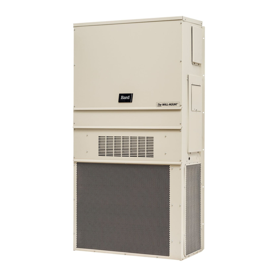
INSTALLATION INSTRUCTIONS
WALL MOUNTED
PACKAGE AIR CONDITIONERS
W17A2
W18A2
W24A2
W30A2
W36A2
W42A2
W48A2
W60A2
W70A2
Bard Manufacturing Company, Inc.
Bryan, Ohio 43506
Since 1914...Moving ahead just as planned.
MODELS
W17L2
W18L2
W24L2
W30L2
W36L2
W42L2
W48L2
W60L2
W70L2
Manual :
2100-581B
Supersedes:
2100-581A
File:
Volume III Tab 16
Date:
11-25-13
Manual
2100-581B
Page
1 of 26
Advertisement
Table of Contents

Subscribe to Our Youtube Channel
Related Manuals for Bard W17A2


Summary of Contents for Bard W17A2
-
Page 1: Wall Mounted
W24L2 W30A2 W30L2 W36A2 W36L2 W42A2 W42L2 W48A2 W48L2 W60A2 W60L2 W70A2 W70L2 Bard Manufacturing Company, Inc. Manual : 2100-581B Bryan, Ohio 43506 Supersedes: 2100-581A File: Volume III Tab 16 Since 1914...Moving ahead just as planned. Date: 11-25-13 Manual 2100-581B... -
Page 2: Table Of Contents
Contents Start Up Getting Other Information and Publications General ............... 15 Topping Off System Charge ........15 Wall Mount General Information Safety Practices ............15 Wall Mount Model Nomenclature ......4 Important Installer Note ........... 16 Shipping Damage ............. 4 High Pressure Switch .......... -
Page 3: Getting Other Information And Publications
GETTING OTHER INFORMATION AND PUBLICATIONS FOR MORE INFORMATION, CONTACT These publications can help you install the air conditioner or heat pump. You can usually find these THESE PUBLISHERS: at your local library or purchase them directly from the publisher. Be sure to consult current edition of each ACCA Air Conditioning Contractors of America standard. -
Page 4: Wall Mount General Information
WALL MOUNT GENERAL INFORMATION AIR CONDITIONER WALL MOUNT MODEL NOMENCLATURE – CONTROL MODULES REVISIONS MODEL NUMBER (See Spec. Sheet S3397) CAPACITY 17 - 1½ Ton VOLTS & PHASE COIL OPTIONS 18 - 1½ Ton A - 230/208/60/1 X - Standard COLOR OPTIONS 24 - 2 Ton B - 230/208/60/3... -
Page 5: Duct Work
Any grille that meets with 5/8 inch louver criteria may be A plastic drain hose extends from the drain pan at used. It is recommended that Bard Return Air Grille Kit the top of the unit down to the unit base. There are... -
Page 6: Installation Instructions
INSTALLATION INSTRUCTIONS WALL MOUNTING INFORMATION WARNING 1. Two holes for the supply and return air openings must be cut through the wall as shown in Figure 3. 2. On wood frame walls, the wall construction must be Failure to provide the 1/4 inch clearance strong and rigid enough to carry the weight of the between the supply duct and a combustible unit without transmitting any unit vibration. -
Page 7: Figure 2 Unit Dimensions
FIGURE 2 Dimensions of Basic Unit for Architectural and Installation Requirements (Nominal) SUPPLY RETURN WIDTH DEPTH HEIGHT MODEL W17A, L W18A, L 33.300 17.125 70.563 7.88 19.88 11.88 19.88 35.00 11.00 25.75 20.56 26.75 28.06 29.25 27.00 2.63 34.13 22.06 10.55 4.19 12.00 5.00... -
Page 8: Figure 3A Mounting Instructions
Manual 2100-581B Page 8 of 26... -
Page 9: Figure 3B Mounting Instructions - W17 - 36
Manual 2100-581B Page 9 of 26... -
Page 10: Figure 3C Mounting Instructions - W42, 48, 60, 70
Manual 2100-581B Page 10 of 26... -
Page 11: Figure 4 Electric Heat Clearance
FIGURE 4 ELECTRIC HEAT CLEARANCE W30A2, W30L2, W36A2, W36L2, W42A2, W42L2, W48A2, W48L2, W60A2, W60L2, W70A2, W70L2 NOTE 1: SIDE SECTION VIEW OF SUPPLY AIR DUCT FOR WALL MOUNTED UNIT SHOWING 1/4 INCH CLEARANCE TO COMBUSTIBLE SURFACES. WARNING A minimum of 1/4 inch clearance must be maintained between the supply air duct and combustible materials. -
Page 12: Figure 5 Wall Mounting Instructions
FIGURE 5 WALL MOUNTING INSTRUCTIONS WALL STRUCTURE SEE FIGURE 3 – MOUNTING INSTRUCTIONS FACTORY SUPPLIED RAIN FLASHING. MOUNT ON UNIT BEFORE INSTALLATION SUPPLY AIR SUPPLY AIR SUPPLY AIR DUCT OPENING OPENING RETURN AIR RETURN AIR RETURN AIR OPENING OPENING OPENING BOTTOM MOUNTING WOOD OR STEEL SIDING BRACKET. -
Page 13: Figure 7 Common Wall Mounting Installations
FIGURE 7 COMMON WALL MOUNTING INSTALLATIONS SUPPLY DUCT MAY BE LOCATED IN AN ATTIC OR BELOW CEILING RAFTERS AS SHOWN RAIN RAIN FLASHING RAFTERS FLASHING RAFTERS FINISHED CEILING SURFACE SUPPLY AIR DUCT SUPPLY AIR DUCT FINISHED CEILING SURFACE W/ GRILLE RETURN AIR RETURN AIR OPENING W/ GRILLE... -
Page 14: Wiring - Main Power
WIRING – MAIN POWER WIRING – LOW VOLTAGE WIRING Refer to the unit rating plate for wire sizing information All 230/208V, 1 phase and 3 phase equipment have and maximum fuse or “HACR” type circuit breaker dual primary voltage transformers. All equipment size. -
Page 15: Start Up
TOPPING OFF SYSTEM CHARGE 8. Store cylinders in a cool area, out of direct sunlight. If a leak has occurred in the system, Bard Manufacturing recommends reclaiming, evacuating 9. Never heat cylinders above 125°F. (see criteria above), and charging to the nameplate 10. -
Page 16: Important Installer Note
START UP (Continued) IMPORTANT INSTALLER NOTE PHASE MONITOR For improved start up performance wash the indoor coil All units with three phase scroll compressors are with a dish washing detergent. equipped with a 3 phase line monitor to prevent compressor damage due to phase reversal. HIGH PRESSURE SWITCH The phase monitor in this unit is equipped with two LEDs. -
Page 17: Sequence Of Operation
SEQUENCE OF OPERATION Alarm Relay Output COOLING – Circuit R-Y makes at thermostat pulling Alarm terminal is output connection for applications where alarm relay is employed. This terminal is in compressor contactor, starting the compressor and outdoor motor. (See NOTE under Condenser Fan powered whenever the compressor is locked out due to Operation if equipped with Low Ambient Control.) The HPC or LPC sequences as described. -
Page 18: Figure 8 Fan Blade Setting
6. Service motor/fan as needed. 7. Reverse steps to reinstall. TABLE 1 FAN BLADE DIMENSION Dimension Model W17A2 / W17L2 W18A2 / W18L2 1.00" W24A2 / W24L2 W30A2 / W30L2 1.25" W36A2 / W36L2... -
Page 19: Cooling Pressure
TABLE 2 COOLING PRESSURE TABLE Air Temperature Entering Outdoor Coil °F Return Air Temp Model Pressure (DB/WB) Low Side 75/62 High Side Low Side W17A/L 80/67 High Side Low Side 85/72 High Side Low Side 75/62 High Side Low Side W18A/L 80/67 High Side... -
Page 20: Electrical Specifications W**A
TABLE 3 Electrical Specifications — W**A Series Single Circuit Dual Circuit Minimum j Maximum Rated Field Circuit External Fuse Field Power Ground Maximum Field MODEL Volts & Minimum Power External Power Ground Ampacity or Ckt. Breaker Wire Size Wire Size Phase... -
Page 21: Table 4 Electrical Specifications W**L
TABLE 4 Electrical Specifications — W**L Series Single Circuit Dual Circuit Minimum j Maximum Rated Field Circuit External Fuse Field Power Ground Maximum Field MODEL Volts & Minimum Power External Power Ground Ampacity or Ckt. Breaker Wire Size Wire Size Phase... -
Page 22: Table 5 Recommended Airflow
TABLE 5 RECOMMENDED AIRFLOW Nominal Nominal Recommended Factory Speed Model Rated Rated Airflow Range Connection CFM * ESP * W17A, W17L 550 - 725 W18A, W18L 550 - 725 W24A, W24L 700 - 950 Single W30A, W30L 1000 850 - 1300 High W36A, W36L 1100... -
Page 23: Table 8 Electric Heat
TABLE 8 ELECTRIC HEAT Models 240V-1 208V-1 240V-3 208V-3 460V-3 Amps BTUH Amps BTUH Amps BTUH Amps BTUH Amps BTUH 16.7 13650 14.4 10240 20.8 17065 18.1 12800 14.4 20500 12.5 15360 20500 33.3 27300 28.8 20475 21.7 30600 18.7 23030 10.8 30700... -
Page 24: Table 9A Optional Accessories - Right Hand
TABLE 9A OPTIONAL ACCESSORIES — RIGHT HAND EHWA02-A05 EHW02A-A08 EHWA02A-A10 EHWA24-A04 EHWA24-B06 EHWH24B-C06 EHWA03-A05 EHWA03-A08 EHWA03-A10 EHWA03-A15 EHWA03-B06 EHW36A-B06 EHWA03-B09 EHWA37-B15 EHWC03A-C06 EHWC03A-C09 EHWA03A-C12 EHWA03A-C15 EHWA05-A05 EHWA05-A10 EHWA05-A15 EHWA05-A20 EHWA05-B09 EHWA05-B15 EHW05A-B18 EHWA05-B18 EHWA05A-C09 EHWA05A-C15 EHWA60-A05 EHW60A-B09 EHW70A-B09 EHW70A-B18 WMCB-01B WMCB-02A WMCB-02B WMCB-03A... -
Page 25: Table 9B Optional Accessories - Left Hand
TABLE 9B OPTIONAL ACCESSORIES — LEFT HAND EHWA02A-A05L EHW02A-A08L EHWA02-A10L EHWA24-B06L EHWA03-A05L EHWA03-A08L EHWA03-A10L EHWA03-A15L EHWA03-B09L EHWA37-B15L EHWC03-C09L EHWA03-C15L EHWA05-A05L EHWA05-A10L EHWA05-A15L EHWA05-B09L EHWA05-B15L EHWA05A-C09L EHWA05A-C15L EHWA60-A05L EHWA60-B09L EHW70A-B09L WMCB-01B WMCB-02A WMCB-02B WMCB-03A WMCB-04B WMCB-05A WMCB-05B WMCB-06B WMCB-08A WMCB-09A WMPD-01C WMCB-09B Manual 2100-581B Page... -
Page 26: Table 10 Vent & Control Options
TABLE 10 VENT & CONTROL OPTIONS Part Number Description CMC-14 CMC-15 Start Kit (230V 1-Phase) CMC-23 CMC-24 CMC-28 BFAD-2 Barometric Fresh Air Damper - Standard BOP-2 Blank Off Plate MFAD-2 Motorized Fresh Air Damper CRV-2 Commercial Ventilator - Spring Return ECONWMS-E2 Economizer - School Version, Enthalpy ECONWMT-E2...
Need help?
Do you have a question about the W17A2 and is the answer not in the manual?
Questions and answers