
Related Manuals for Honeywell HCCM474M


Summary of Contents for Honeywell HCCM474M
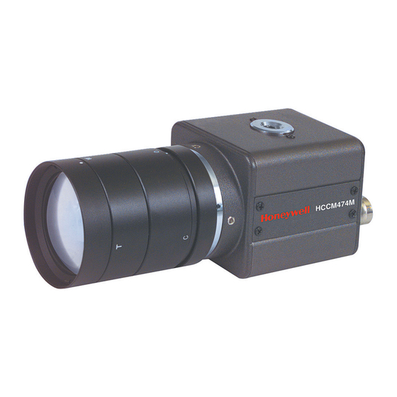
- Page 1 HCCM474M ULTRA MINIATURE 1/3’’ COLOR CAMERA WITH LOW LIGHT B/W MODE REV. B HCMU000878 12/29/03...
- Page 2 93/68/EEC)] and Electromagnetic rules. Changes or modifications not Compatibility Directives [(89/336/EEC, 92/31/EEC) and approved by Honeywell could void (93/68/EEC)] are fulfilled as laid out in the guideline set the user’s authority to operate the down by the member states of the EEC Commission.
-
Page 3: Table Of Contents
Thank you for purchasing the Honeywell Ultra Miniature color CCD camera. Before using this camera please read the manual carefully to obtain the best results and keep the manual for future reference. TABLE OF CONTENTS PRECAUTIONS ................................4 FEATURES ..................................6 CONTROLS AND CONNECTIONS ..........................8 Camera Side................................8... -
Page 4: Precautions
PRECAUTIONS Operating • Before using, check power supply and video output connection. • Power supplied without voltage stabilization or the voltage maintained at 24V±10%AC or 12V±10%DC may cause damage. • If any abnormal condition or malfunction is observed while operating the camera, stop using it immediately and call your local dealer. - Page 5 PRECAUTIONS, CONTINUED Installation and storage • Do not point the camera at the sun. This could damage the camera whether it is operating or not. • Do not install the camera where the temperature could exceed the allowable range. • Ambient temperature should be less than 40°C for long-term continuous operation.
-
Page 6: Features
FEATURES High Sensitivity • 1/3” 410,000 pixels CCD with on-chip micro lenses and low noise signal processing circuit provide high sensitivity down to 0.4 lux (F1.2, 50IRE). High Quality Image • High resolution, high sensitivity design for a horizontal resolution of 470 TV lines (NTSC)/460 TV lines (PAL). - Page 7 FEATURES, CONTINUED White Balance • Three control modes of auto-tracking preset and manual white balance can be selected according to conditions. Iris Function • Provides a drive output for video iris lens. • Built-in electronic shutter allows 11 shutter speeds up to 1/100,000 sec. •...
-
Page 8: Controls And Connections
CONTROLS AND CONNECTIONS Camera Side 2. Backfocus screw 1. Lens mount HCCM474M 4. 1/4-20 mounting base 3. Lens mount cap (camera top and bottom) REV. B HCMU000878 12/29/03... - Page 9 CONTROLS AND CONNECTIONS, CONTINUED Camera Side, continued 1. Lens mount Used when installing the lens. A C-mount lens can be used when C-mount adapter is attached. CS-mount lens can be used when adapter is removed. 2. Backfocus screw A screw is provided to fix the lens mount. 3.
-
Page 10: Camera Back
CONTROLS AND CONNECTIONS, CONTINUED Camera Back 1. Lens Switch 4. Power Indicator VIDEO 2. Lens 5. Setup buttons Connector 6. Power Input LENS Terminal 3. Video output connector VIDEO REV. B HCMU000878 12/29/03... - Page 11 CONTROLS AND CONNECTIONS, CONTINUED Camera Back, continued 1. Lens switch Used to switch between DC and Video lenses. 2. Lens connector When using an auto-iris lens, connect the lens cable to this connector. 3. Video output connector BNC connector that outputs a composite video signal. 4.
-
Page 12: Menu Operation
MENU OPERATION • The menu system can activate all of the fea- MENU OPERATION tures and options of the camera. Five buttons on the rear panel are used to shift the cursor and select • The menus are superimposed on the image items on the menus. -
Page 13: Menu Description
Menu Description AGC control MAIN MENU (page 16) Lens selection & (page 14) level set (page 15) SHUTTER WHITE BACK TEXT SYNC SPECIAL BALANCE LIGHT DISPLAY MODE MENU (page 17) (page 19) (page 21) (page 23) (page 24) (page 26) Shutter mode select Back light compensation Sync mode control... -
Page 14: Main Menu
MAIN MENU MAIN MENU MAIN MENU Press the SET button to display the MAIN MENU on the ➔ Lens : DC monitor screen. : 32dB Check the present settings at the main menu. Shutter : AUTO White Balance : ATW If no changes are needed, move the cursor to the End Back Light : OFF... -
Page 15: Lens
MAIN MENU, CONTINUED Lens MAIN MENU ➔ Lens : DC Press the Set button to display the MAIN MENU. : 32dB Position the cursor at LENS and press the left or right button Shutter : AUTO White Balance : ATW for setting the lens mode. -
Page 16: Agc
MAIN MENU, CONTINUED MAIN MENU Lens : DC Press the Set button to display the main menu. ➔ : 32dB Position the cursor at AGC and press the left or right button Shutter : AUTO to setting the AGC max level. White Balance : ATW AGC max level has 8 stage from OFF to 32dB. -
Page 17: Electronic Shutter Control
MAIN MENU, CONTINUED Electronic Shutter Control MAIN MENU 1. Press SET to display the MAIN MENU. Lens : DC : 32dB 2. Position the cursor at Shutter, and press the left or right button ➔ Shutter : AUTO to set the manual shutter. White Balance : ATW Back Light... - Page 18 MAIN MENU, CONTINUED MANUAL Mode Press SET to set the manual shutter speed when the MANUAL SHUTTER cursor is at Shutter and shutter mode is manual. ➔ Shutter Speed : 1/60 Press the left or right direction button to select a shutter Press SET to Main Menu speed from 1/60 to 1/100,000 sec.
-
Page 19: White Balance Control
MAIN MENU, CONTINUED White Balance Control MAIN MENU Lens : DC 1. Press SET to display the MAIN MENU on the monitor : 32dB screen. Shutter : AUTO 2. Position the cursor at WHITE BALANCE and press the left ➔ White Balance : ATW Back Light... - Page 20 MAIN MENU, CONTINUED AWC (PRESET WHITE BALANCE) With a white object present in the scene, press SET then position the cursor at White Balance and set to AWC. Setting the preset white balance takes several seconds and the selection is complete when the message "White Balance Completed"...
-
Page 21: Back Light Compensation
MAIN MENU, CONTINUED Back Light Compensation MAIN MENU Lens : DC : 32dB Strong light, such as from a spotlight or window, entering the Shutter : AUTO scene background causes the lens iris to close, possibly White Balance : ATW obscuring desired portions of the scene. - Page 22 MAIN MENU, CONTINUED BLC Zone Setting BLC ZONE SET ➔ Zone Display Backlight control uses 6 sensing zones. Zone 1 :OFF The BLC Zone setting is activated on the screen with either the Zone 2 :OFF left or right button to allow the most suitable area to be selected Zone 3 :OFF Zone 4...
-
Page 23: Text Display
MAIN MENU, CONTINUED Text Display MAIN MENU Lens : DC Press SET to display the MAIN MENU. : 32dB Move the cursor to TEXT DISPLAY and use the left and Shutter : AUTO right buttons to toggle between the ON and OFF settings. White Balance : ATW Back Light... - Page 24 MAIN MENU, CONTINUED Text Location Camera 1 Text location is set by selecting POS from the TEXT GEN- ERATION menu and pressing SET. Use the left, right, up, and down buttons to move text location. After selecting text location, press SET to return to the to Locate, then SET MAIN MENU.
- Page 25 MAIN MENU, CONTINUED LINE LOCK PHASE ADJUSTMENT LINE LOCK PHASE Press SET to adjust line-lock phase when the cursor is at SYNC MODE and the mode is set to L.L. ➔ Phase 135 degree Press the left or right direction button to adjust line-lock phase.
-
Page 26: Special Menu
MAIN MENU, CONTINUED Special Menu MAIN MENU Lens : DC : 32dB The Special Menu is used to change the video output settings to Shutter : AUTO match particular applications. White Balance : ATW Press SET to display the MAIN MENU. Back Light : OFF Text Display... - Page 27 MAIN MENU, CONTINUED GAMMA GAMMA ADJUSTEMENT ➔ Level 14 Position the cursor at GAMMA and press SET. Use the left, right, up, and down buttons to set the Gamma Level gamma value level. Gamma level can be set to a maximum of 32 steps, 0.45 according to conditions.
- Page 28 MAIN MENU, CONTINUED Day/Night SPECIAL MENU This feature is useful when want to lighten a dark image. Gamma At this mode, video signal increase the gain by 8dB. Color Adj Position the cursor at Day/Night and press the eft or right ➔...
- Page 29 MAIN MENU, CONTINUED Sharpness SPECIAL MENU Gamma Position the cursor at SHARPNESS and use the right and Color Adj left buttons to toggle between HIGH and LOW. Day/Night : Auto ➔ Move the cursor up or down and SET to select the Sharpness : LOW Contrast...
- Page 30 MAIN MENU, CONTINUED Brightness BRIGHTNESS Position the cursor at BRIGHTNESS and press SET. ➔ Level 00 Use the left and right buttons to adjust levels. Press SET to Return Once values are selected, press SET to return to the SPECIAL MENU. SPECIAL MENU Gamma Color Adj...
- Page 31 MAIN MENU, CONTINUED Preset SPECIAL MENU Gamma The Preset function is useful when the camera setup conditions Color Adj are frequently changed. Preset provides the best image under Day/Night : Auto normal conditions as set by the factory. Sharpness : LOW Contrast : OFF Position the cursor at Preset and press SET.
-
Page 32: Lens Installation And Adjustment
LENS INSTALLATION AND ADJUSTMENT When using an auto-iris lens, install the accessory lens plug on to the lens cable as follows. Video type lens ; Set lens switch to VIDEO. Connect the lens cable of a video type lens. V I D If the plug on the cable is of a different type, replace it with the provided 4-pin iris plug. - Page 33 LENS INSTALLATION AND ADJUSTMENT, CONTINUED DC type lens ; Set lens switch to DC. Connect the lens cable of a DC (galvanometric) type lens. If the plug on the cable is of a different type, replace it with the provided 4-pin iris plug. Drive coil (+) Damping coil (-) Damping coil (+)
-
Page 34: Mounting A Lens
LENS INSTALLATION AND ADJUSTMENT, CONTINUED Mounting a Lens Remove the lens mount cap from the camera. Attach or remove the C-mount adapter depending on the lens to be used. Attach the lens to the lens mount. Secure it so that it does not become loose. If the lens has an auto-iris mechanism, connect the lens cable to the lens connector. -
Page 35: Backfocus Adjustment
Adjust with the lens focus ring when the correct focus cannot be obtained. (Refer to the table on the next page.) An ND filter may be HCCM474M used to open the iris ofthe auto iris lens when adjusting the backfocus. - Page 36 LENS INSTALLATION AND ADJUSTMENT Backfocus Adjustment With A Backfocus Adjustment With A Fixed-Focus Lens Zoom Lens Fully open the aperture and set the focus ring Fully open the aperture and set the lens to the to ∞ (infinity). If using an auto-iris lens, shoot a maximum telephoto position, then turn the focus ring to focus.
-
Page 37: Specifications
SPECIFICATIONS ITEMS SPECIFICATIONS Signal format NTSC CCD Pickup element Interline transfer 1/3" CCD Effective pixels NTSC: 768(H) x 494(V) Scanning area 7.95(H) x 6.45(V) mm Scanning system 2:1 interlace Scanning frequency NTSC: Horizontal: 15.743kHz / Vertical: 59.94Hz Video output Composite video signal: 1Vp-p, 75Ohm, unbalanced Video S/N ratio 50dB (AGC OFF) Horizontal resolution... - Page 38 SPECIFICATIONS, CONTINUED ITEMS SPECIFICATIONS Auto electronic shutter ON/OFF selectable (1/60~1/100,000 second) (NTSC:1/60~1/100,000 second PAL:1/50~1/100,000 second) 1/60 (1/50 PAL), 1/100, 1/120, 1/250, 1/500, 1/1000, 1/2000, Shutter speed range 1/4000, 1/10000, 1/30000, 1/50000, 1/100000 second White balance Selectable auto-tracking (ATW), preset (AWC), and MANUAL Backlight compensation ON/OFF selectable (6 sensing zones) Text display...
- Page 39 SPECIFICATIONS, CONTINUED ITEMS SPECIFICATIONS Power consumption Max 3 watts Operating temperature 14°F to 122°F (-10°C to +50°C) Operating humidity less than 85% relative humidity Storage temperature -4°F to 140°F (-20°C to +60°C) Dimensions 1.6W x 1.6H x 2.8D inches (41W x 41H x 73D mm) Weight 0.35 lbs (160g) Notes:...
-
Page 40: Supplied Accessories
SUPPLIED ACCESSORIES Lens mount cap C-mount adapter L-wrench User manual For Customer Use : please record the Model No. and Serial No. in the spaces provided below. These numbers are located on the bottom of the camera. Keep this manual for future reference. Model No. -
Page 41: Honeywell Video Systems
HONEYWELL VIDEO SOLUTIONSS South Africa Honeywell Video Solutions 53 Juta Street 1305 Waters Ridge Drive Braamfontein Lewisville, TX 75057 2001 South Africa +1-800-796-2288 + 27-11-403-3002 www.honeywellvideo.com www.teqtrader.com United Kingdom Italy Aston Fields Rd. Via della Resistenza, 53/59 Whitehouse Ind. Est 1 –...
Need help?
Do you have a question about the HCCM474M and is the answer not in the manual?
Questions and answers