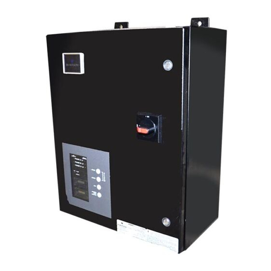
Summarization of Contents
Unpacking and Installation
Unpacking and Preliminary Inspection
Inspect shipping crate and unit for damage before unpacking. File claims if damage is observed.
Handling and Storage
Guidelines for handling units on pallets and proper storage environment and temperature.
Location Considerations
Environment and Clearances
Details operating environment, audible noise levels, and required service clearances.
Safety Warnings Defined
Explanation of DANGER, WARNING, and CAUTION signal words and their safety implications.
Model Number Configuration
Series and Configuration Codes
Explains how series and configuration/voltage codes form the model number.
Protection Modes and Enclosure Types
Details available protection modes and enclosure types for model configuration.
UL Type and Accessories
Specifies UL 1449 types and available accessories for model configuration.
Configuration & Voltage Chart
Single Phase Configurations
Details voltage and configuration codes for single-phase systems.
Three Phase DELTA Configurations
Details voltage and configuration codes for three-phase Delta systems.
Three Phase WYE Configurations
Details voltage and configuration codes for three-phase Wye systems.
Electrical Connections
Voltage and Power Source Matching
Ensure unit voltage rating matches the intended power source.
Wiring Practices and NEC Compliance
Covers wire connection best practices, NEC requirements, and VPR implications.
Grounding and Bonding
Details system grounding, bonding, electrode requirements, and neutral connection importance.
Parallel Connection Diagram
Provides a wiring diagram for parallel SPD connections.
Installation Instructions
Pre-Installation and Wiring
Covers power removal, wiring connections, and enclosure mounting.
Operational Status Indicators (LEDs)
Explains LED indicators for normal and fault conditions and troubleshooting steps.
Module Replacement and Support
Information on replacing protection modules and contacting support.
Suggested Circuit Breaker and Wire Size
Manufacturer Recommendations
Provides suggested circuit breaker sizes and wire gauges based on surge rating.
Dimensional Information
Presents physical dimensions and weight for different series and connection types.
Motorola R56 Approved Models
Circuit Breaker and Wire Size
Specific recommendations for Motorola R56 approved models.
Dimensional Information
Physical dimensions and weight for R56 approved models.
Monitoring Features
External Status Indicators
Describes LED indicators for system status (OK, Service).
Summary Alarm Contacts
Details Form C relay contacts for remote alarm indication.
Audible Alarm and Test Feature
Explains audible alarms, disable function, and the test feature for surge modules.
Surge Counters and Active Monitor
Information on surge counters for monitoring and the optional Active Surge Monitor.
Troubleshooting, Servicing, and Maintenance
Troubleshooting Common Issues
Steps to take when status failure indications or alarm contacts change state.
Servicing and Warranty
Contact information for servicing assistance and warranty details.
Corrective and Preventative Maintenance
Guidelines for repairing failed units and performing periodic inspections and cleaning.


Need help?
Do you have a question about the 560 and is the answer not in the manual?
Questions and answers