
Related Manuals for Emerson 500 Series


Summary of Contents for Emerson 500 Series
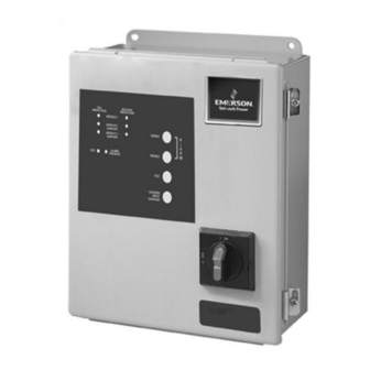
- Page 1 500 Series 510 Surge Protective Device Installation, Operation and Maintenance Manual...
-
Page 2: Table Of Contents
Surge Protective Devices EMERSON NETWORK POWER SURGE PROTECTIVE DEVICE INSTALLATION, OPERATION AND MAINTENANCE MANUAL TABLE OF CONTENTS UNPACKING AND INSTALLATION Unpacking and Preliminary Inspection ..............2 Handling Considerations . -
Page 3: Unpacking And Installation
For interconnected electronic loads (such as by way of forward a copy to your local Emerson Network Power data cabling), transient surge suppression should also be Surge Protection Sales Representative. -
Page 4: Model Number Configuration
Surge Protective Devices MODEL NUMBER CONFIGURATION Model #: _ _ _ _ _ _ _ _ _ _ _ _ _ (1-3) Series (8) Modes of Protection (11) Enclosure 510 = Modular/Non-Modular MOV A = All Modes of Protection R = Type 3R (metal) B = L-N &... -
Page 5: Electrical Connections
Surge Protective Devices ELECTRICAL CONNECTIONS All electrical connections should be installed by a qualified (1) Grounded service conductor (licensed) electrician only. All wiring must comply with the (2) Grounded electrode conductor National Electrical Code (NEC) and applicable local (3) Grounding electrode for service codes. -
Page 6: Parallel Connections
Surge Protective Devices PARALLEL CONNECTIONS Typical Parallel Connections Typical Parallel Connections (without Internal Rotary Disconnect) (with Internal Rotary Disconnect) Protected Loads Protected Loads Neutral Surge Protective Phase(s) Device Neutral Surge Transient Ground Protective Rotary Phase(s) Device Disconnect Protected Safety Ground Panel Wire should be Transient... -
Page 7: Installation Instructions
Surge Protective Devices INSTALLATION INSTRUCTIONS The Emerson Network Power 510 Series Surge Protective 6. Apply power. The surge protector is fully operational Devices (SPDs) are high quality, high energy surge current when the GREEN LED s on the modules (when applicable), and diversion systems designed to protect sensitive equipment the front of the enclosure are illuminated. -
Page 8: Nema 12 (Metal) Enclosure Option
Surge Protective Devices NEMA 12 (Metal) Enclosure Option SUGGESTED CIRCUIT BREAKER AND WIRE SIZE Allowable Range Factory Suggested Size Surge Rating Connection Wire Size Connection Circuit Breaker Size Circuit Breaker Per Mode Wire Size Size With Disconnect Without Disconnect With Disconnect Without Disconnect 60kA-80kA 40 Amp... -
Page 9: Nema 1 Panelboard Extension Enclosure Option
Surge Protective Devices NEMA 1 Panelboard Extension Enclosure Option SUGGESTED CIRCUIT BREAKER AND WIRE SIZE Overcurrent Protection (Circuit Breaker): Allowable Range: 15A - 100A Suggested Size: 30A Connection Wire: Allowable Range: #14 - #2 Suggested Size: #10 Weight: 30 lb. (13.6 kg) Summary Alarm Contacts Connection shall be with #18 22 AWG. -
Page 10: Monitoring Features
Servicing External Status Indicators (Standard) These indicators The Emerson Network Power 510 Series comes with a provide a summary of the status of the surge SPD ten year warranty. For servicing assistance, contact your module. For normal conditions, the green OK LED is local Sales Representative or Emerson Network Power, illuminated and the red Service LED is extinguished. -
Page 11: Installation, Operation And Maintenance Manual 1 Io-70103 Rev 0, 1/2013
Technical Support 800 288 6169 Toll-Free 607 721 8840 Phone 607 722 8713 FAX © 2012 Emerson Network Power. All rights reserved throughout the world. Specifications subject to change without notice. IO-70103 Rev 0, (1/2013) Printed in USA IO-70103 Rev 0, 1/2013...
Need help?
Do you have a question about the 500 Series and is the answer not in the manual?
Questions and answers