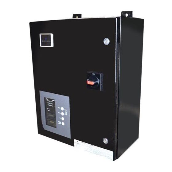
Summarization of Contents
Unpacking and Installation
Unpacking and Preliminary Inspection
Procedure for inspecting shipping crates and units for damage before unpacking.
Handling Considerations
Guidance on handling larger units bolted to shipping pallets using forklifts or pallet jacks.
Storage
Recommendations for storing the unit in a clean, dry environment with specified temperature ranges.
Location Considerations
Environment
Specifies the intended operating environment for the unit, including temperature and humidity limits.
Audible Noise
Details the noise level of the unit and its suitability for various room placements.
Service Clearances
Recommends minimum clearance requirements for units with hinged doors for proper access.
Mounting
Information regarding the unit's intended wall mounting and reference to installation instructions.
Warnings Defined
Defines safety warning signals (DANGER, WARNING, CAUTION) and their implications for injury and damage.
Model Number Configuration
Model Number Configuration Details
Breaks down the model number structure for series, configuration, voltage, surge rating, and options.
Active Surge Monitor Option
Information on the optional web-based monitoring device for real-time power quality analysis.
Configuration & Voltage Chart
Single Phase Configurations
Details voltage configurations and corresponding model number codes for single-phase power sources.
Three Phase Delta Configurations
Details voltage configurations and corresponding model number codes for three-phase delta power sources.
Three Phase Wye Configurations
Details voltage configurations and corresponding model number codes for three-phase Wye power sources.
Electrical Connections
Voltage Ratings and Power Source Configurations
Verifying unit voltage rating against the intended power source before making connections.
Wire Connections
Guidelines for connecting conductors, including recommended wire size and routing for impedance reduction.
Overcurrent Protection
Explanation of the SPD's minimal current draw under normal operation and transient surge currents.
NEC Considerations
References to the National Electric Code (NEC) for compliance in wiring and installation practices.
NEC 285.21 Connections and NEC 285.23 Type 1 SPD Installation
Specific NEC requirements for Type 1 SPD connections at the service entrance and Type 2 locations.
Voltage Protection Ratings
Information on obtaining VPRs as per UL standards and the impact of conductor wire size.
Circuit Ampacity Limitations
Details UL investigation findings on the product's ability to withstand system voltages and fault currents.
System Grounding and Bonding
Emphasizes the critical role of proper grounding and bonding for SPD performance and safety.
Grounding Electrode
Explains how SPDs divert surge current and the importance of a compliant service entrance grounding electrode system.
Neutral Connection
Notice highlighting the requirement for a reliable neutral connection for proper and safe operation.
Parallel Connection / Wire Diagram
Provides a schematic diagram illustrating the parallel connection of the SPD to the AC source.
Installation Instructions
General Installation Steps
Comprehensive steps for qualified personnel, covering power removal, mounting, and wiring connections.
Summary Alarm Contacts
Details on connecting the unit's summary alarm contacts, including wire gauge and contact ratings.
Wiring Diagram Reference
Visual reference for connecting the SPD within the service panel, showing key connection points.
Suggested Circuit Breaker and Wire Size
For Motorola R56 Approved Models
Provides specific circuit breaker and wire size recommendations for Motorola R56 approved models.
Dimensional Information
570 Series Dimensions
Presents dimensional data (A, B, C, D) and weight for the 570 Series SPD models.
560 Series Dimensions
Presents dimensional data (A, B, C, D) and weight for the 560 Series SPD models.
Motorola R56 Approved Models
Suggested Circuit Breaker and Wire Size
Specific recommendations for circuit breaker and wire size for Motorola R56 approved models.
Dimensional Information
Provides key dimensions and weight for various Motorola R56 approved SPD model numbers.
Monitoring Features
External Status Indicators (Standard)
Describes standard indicators (Green OK, Red Service) that provide module status and fault indication.
Summary Alarm Contact (Standard)
Details the Form C relay contacts for remote indication of a failed surge SPD module.
Audible Alarm (when included)
Explains the audible alarm function for indicating module replacement needs and its disable feature.
Single/Dual Surge Counter (when included)
Describes surge counters for monitoring transient voltage surges and their line deviation settings.
Test Feature (when included)
Details the SPD test feature for self-checking fuse links and determining remaining protection percentage.
Active Surge Monitor (Optional)
Overview of the optional web-based device for real-time power quality measurements and event logging.
Troubleshooting/Servicing/Maintenance
Troubleshooting
Guidance on diagnosing status failure indications or alarm conditions and when to consult the factory.
Servicing
Information on warranty and contact details for obtaining servicing assistance from Emerson Network Power.
Corrective Maintenance
Guidance on repairing or replacing failed units or surge modules and inspecting other components.
Preventative Maintenance (Inspection and Cleaning)
Recommendations for periodic inspections, cleaning, and connection checks to ensure reliable performance.


Need help?
Do you have a question about the 570 and is the answer not in the manual?
Questions and answers