Table of Contents
Advertisement
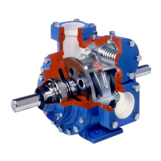
BLACKMER LIQUEFIED GAS PUMPS
FOR LP-GAS AND NH
INSTALLATION OPERATION AND MAINTENANCE INSTRUCTIONS
MODELS: LGLD2E, LGL2E, LGLD3F, LGL3F
and discontinued LGLD3E, LGL3E
TABLE OF CONTENTS
SAFETY DATA ..................................................................... 1
Pump Identification ..................................................... 2
Technical Data ........................................................... 2
Initial Pump Start Up Information ............................... 2
Welded Connections .................................................. 3
Pre-Installation Cleaning ............................................ 3
Location and Piping .................................................... 3
Pump Relief Valve and Bypass Valve ........................ 4
Check Valves ............................................................. 4
Pump Rotation ........................................................... 4
Pump Mounting .......................................................... 4
Coupling Alignment .................................................... 5
V-Belt Drive ................................................................ 5
V-Belt Disassembly .................................................... 5
Pre-Start Up Check List ............................................. 6
Start Up Procedures ................................................... 6
TRUCK MOUNTED PUMPS
Truck Mounting .......................................................... 6
Pump Drive ................................................................ 6
Hydraulic Drive ........................................................... 7
Pre-Start Up Check List ............................................. 7
Start Up Procedures ................................................... 7
Pump Speed .............................................................. 8
Strainers ..................................................................... 8
Lubrication ................................................................. 8
Vane Replacement ..................................................... 9
Pump Disassembly .................................................... 9
Pump Assembly ....................................................... 10
TROUBLE SHOOTING ...................................................... 12
NOTE: Numbers in parentheses following individual parts
indicate reference numbers on Blackmer Parts List 501-C01
Blackmer pump manuals and parts lists may be obtained from
Blackmer's website (www.blackmer.com) or by contacting
Blackmer Customer Service.
SERVICE TRUCK AND BASE MOUNTED
3
Page
960417
INSTRUCTIONS NO. 501-C00
SAFETY DATA
This is a SAFETY ALERT SYMBOL.
When you see this symbol on the product, or in the manual,
look for one of the following signal words and be alert to the
potential for personal injury, death or major property
damage
Warns of hazards that WILL cause serious personal injury,
death or major property damage.
Warns of hazards that CAN cause serious personal injury,
death or major property damage.
Warns of hazards that CAN cause personal injury
or property damage.
NOTICE:
Indicates special instructions which are very
important and must be followed.
NOTICE:
Blackmer liquefied gas pumps MUST only be installed
in systems which have been designed by qualified
engineering personnel. The system MUST conform to
all applicable local and national regulations and safety
standards.
This manual is intended to assist in the installation and
operation of the Blackmer liquefied gas pumps, and
MUST be kept with the pump.
Blackmer liquefied gas pump service shall be
performed by qualified technicians ONLY. Service shall
conform to all applicable local and national regulations
and safety standards.
Thoroughly review this manual, all Instructions and
hazard warnings, BEFORE performing any work on the
Blackmer liquefied gas pumps.
Maintain ALL system and Blackmer liquefied gas pump
operation and hazard warning decals.
Section
501
Effective
Apr 2020
Replaces
Jan 2019
Advertisement
Table of Contents

Related Manuals for BLACKMER LGL3F


Summarization of Contents
Safety Data
General Safety Warnings
Overview of safety alert symbols and their meanings for hazard communication.
Specific Operational Warnings
Detailed warnings regarding hazardous machinery, voltage, pressure, and fluids.
Pump Data
Pump Identification
Details on locating and recording pump identification tag information for reference.
Technical Data
Specifications for LGLD2E, LGL2E, LGLD3F, LGL3F models including torque, speed, and pressure.
Initial Pump Start Up Information
Fields for recording model, serial, ID, installation date, and gauge readings.
General Installation and Operation
Welded Connections
Instructions for handling O-rings during welding to prevent damage.
Pre-Installation Cleaning
Guidance on flushing new pumps and cleaning supply tanks and intake piping.
Location and Piping
Recommendations for optimal pump placement, inlet piping, strainers, and leak prevention.
Pump Relief Valve and Bypass Valve
Details on the function and installation of internal and external bypass valves.
Check Valves
Discussion on the recommendation against check valves in supply tanks.
Pump Rotation
Instructions on how to confirm and change pump rotation direction.
Motor Driven Pumps
Pump Mounting
Guidelines for permanently mounting the pump unit on a level concrete floor.
Coupling Alignment
Procedures for ensuring proper parallel and angular alignment of coupled shafts.
V-Belt Drive
Steps for installing, aligning, and tensioning V-belts for optimal performance.
V-Belt Disassembly
Instructions for safely removing V-belts, sheaves, and hubs.
Pre-Start Up Check List
Checklist for verifying piping, alignment, gauges, and valve positions before start-up.
Start Up Procedures
Step-by-step guide for starting the pump, checking parameters, and inspecting for leaks.
LGLD Truck Mounted Pumps
Truck Mounting
Considerations for safely locating and mounting the pump on a truck frame.
Pump Drive
Guidelines for using power take-off, universal joints, and jack shafts for pump drive.
Hydraulic Drive
Details on driving LGLD pumps with hydraulic motors and alignment requirements.
Pre-Start Up Check List
Checks for pipe alignment, pressure gauges, and hose connections before operation.
Start Up Procedures
Steps for starting the pump, checking flow rates, pressures, and relief valve operation.
Pump Speed
Requirement for speed control devices to prevent exceeding maximum RPM specifications.
Maintenance
Strainers
Importance of regular strainer cleaning to prevent pump starvation.
Lubrication
Guidance on lubricating pump bearings and hydraulic motors, and recommended greases.
Vane Replacement
Step-by-step instructions for replacing worn pump vanes and push rods.
Pump Disassembly
Detailed instructions for disassembling the pump, including head, bearing, and seal removal.
Pump Assembly
Procedures for reassembling the pump, including liner, disc, seals, and bearings.
Mechanical Seal Installation
Instructions for installing rotating and stationary mechanical seal components.
Locknut Adjustment
Procedure for properly adjusting bearing locknuts to prevent damage and wear.
Trouble Shooting
Pump Not Priming
Common causes and probable solutions for pumps failing to prime.
Reduced Capacity
Potential reasons for decreased pump capacity and how to address them.
Damaged Vanes
Causes of vane damage such as foreign objects, dry running, or incorrect installation.
Broken Shaft
Possible causes for a broken shaft, including foreign objects, misalignment, and cavitation.
Mechanical Seal Leakage
Factors contributing to mechanical seal leakage, like incompatible O-rings or worn parts.
Overload on Motor
Reasons for motor overload, including insufficient horsepower, misalignment, or bearing issues.
Need help?
Do you have a question about the LGL3F and is the answer not in the manual?
Questions and answers