Table of Contents
Advertisement
Quick Links
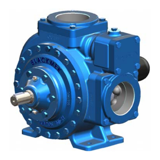
BLACKMER LIQUEFIED GAS PUMPS
FOR LP-GAS AND NH
INSTALLATION OPERATION AND MAINTENANCE INSTRUCTIONS
Patent Protected by U.S. Patent 6030191 and Related Foreign Patents.
TABLE OF CONTENTS
SAFETY DATA ..................................................................... 1
Pump Identification ..................................................... 2
Technical Data ........................................................... 2
Initial Pump Start Up Information ............................... 2
Welded Connections .................................................. 3
Pre-Installation Cleaning ............................................ 3
Location and Piping .................................................... 3
Pump Relief Valve and Bypass Valve ........................ 4
Check Valves ............................................................. 4
Pump Rotation ........................................................... 4
Pump Mounting .......................................................... 4
Coupling Alignment .................................................... 5
V-Belt Drive ................................................................ 5
V-Belt Disassembly .................................................... 5
Pre-Start Up Check List ............................................. 6
Start Up Procedures ................................................... 6
Truck Mounting .......................................................... 6
Pump Drive ................................................................ 6
Hydraulic Drive ........................................................... 7
Pre-Start Up Check List ............................................. 7
Start Up Procedures ................................................... 7
Pump Speed .............................................................. 8
Strainers ..................................................................... 8
Lubrication .................................................................. 8
Vane Replacement ..................................................... 9
Pump Disassembly .................................................... 9
Pump Assembly ....................................................... 10
TROUBLE SHOOTING ...................................................... 11
NOTE: Numbers in parentheses following individual parts
indicate reference numbers on Blackmer Parts List 501-L01
Blackmer pump manuals and parts lists may be obtained from
Blackmer's website (www.blackmer.com) or by contacting
Blackmer Customer Service.
SERVICE, TRUCK AND BASE MOUNTED
3
MODEL: LGL3021A
Page
960439
INSTRUCTIONS NO. 501-L00
SAFETY DATA
This is a SAFETY ALERT SYMBOL.
When you see this symbol on the product, or in the manual,
look for one of the following signal words and be alert to the
potential for personal injury, death or major property damage
Warns of hazards that WILL cause serious personal injury,
death or major property damage.
Warns of hazards that CAN cause serious personal injury,
death or major property damage.
Warns of hazards that CAN cause personal injury
or property damage.
NOTICE:
Indicates special instructions which are very
important and must be followed.
NOTICE:
Blackmer liquefied gas pumps MUST only be installed
in systems which have been designed by qualified
engineering personnel. The system MUST conform to
all applicable local and national regulations and safety
standards.
This manual is intended to assist in the installation
and operation of the Blackmer liquefied gas pumps,
and MUST be kept with the pump.
Blackmer liquefied gas pump service shall be
performed by qualified technicians ONLY. Service
shall conform to all applicable local and national
regulations and safety standards.
Thoroughly review this manual, all Instructions and
hazard warnings, BEFORE performing any work on
the Blackmer liquefied gas pumps.
Maintain ALL system and Blackmer liquefied gas
pump operation and hazard warning decals.
Section
501
Effective
Jun 2016
Replaces
Jan 2014
Advertisement
Table of Contents

Related Manuals for BLACKMER LGL3021A


Summary of Contents for BLACKMER LGL3021A
-
Page 1: Table Of Contents
Maintain ALL system and Blackmer liquefied gas indicate reference numbers on Blackmer Parts List 501-L01 pump operation and hazard warning decals. Blackmer pump manuals and parts lists may be obtained from Blackmer's website (www.blackmer.com) or by contacting Blackmer Customer Service. -
Page 2: Pump Data
A pump Identification tag, containing the pump serial number, I.D. number, and model designation, is attached to each pump. It is recommended that the data from this tag be recorded and filed for future reference. If replacement parts are needed, or if information pertaining to the pump is required, this data must be furnished to a Blackmer representative. TECHNICAL DATA INITIAL PUMP START UP INFORMATION Model No.: ____________________________________... -
Page 3: General Installation And Operation
GENERAL INSTALLATION AND OPERATION NOTICE: LOCATION AND PIPING Blackmer pumps must only be installed in systems Pump life and performance will be significantly reduced when designed by qualified engineering personnel. System installed in an improperly designed system. Before starting design must conform with all applicable regulations and the layout and installation of the piping system, review the codes and provide warning of all system hazards. -
Page 4: Pump Relief Valve And Bypass Valve
Blackmer LGL3021 pump model has a double ended rotor approximately 150 PSI (10.3 bar). and shaft, enabling them to be driven from either shaft end. -
Page 5: Coupling Alignment
Operation without guards in place can V-BELT DRIVE cause serious personal injury, major For installation of Blackmer V-belt units, first mount the pump property damage, or death. and the motor base to the unit base. Do not fully tighten the... -
Page 6: Pre-Start Up Check List
MOTOR DRIVEN PUMPS Check the flow rate to ensure the pump is operating PRE-START UP CHECK LIST within the expected parameters. Record flow rate in the Inspect complete piping system and supports to ensure “Initial Start Up” section of this manual. that no piping loads are being placed on the pump. -
Page 7: Hydraulic Drive
Truck mounted pumps may also be driven hydraulically. the pump rotation arrows. Hydraulic motors must be well supported with their shafts parallel to the pump shaft in all respects. Blackmer provides Check the pump speed. Pump speed must never exceed an optional close-coupled hydraulic motor adapter. The the recommended maximum. -
Page 8: Pump Speed
TRUCK MOUNTED PUMPS PUMP SPEED PTO and hydraulically driven units MUST contain speed control devices to prevent pump speeds above the maximum RPM specifications, regardless of the truck engine unloading speeds. Should fluid delivery be appreciably less than expected, see the "General Pump Troubleshooting"... -
Page 9: Vane Replacement
MAINTENANCE To remove locknuts and lockwashers (24A and 24B): VANE REPLACEMENT Bend up the engaged lockwasher tang and rotate NOTICE: the locknut (24A) counterclockwise to remove it from Maintenance shall be performed by qualified technicians the shaft only, following the appropriate procedures and warnings Slide the lockwasher (24B) off the shaft. -
Page 10: Pump Assembly
MAINTENANCE PUMP ASSEMBLY After the bottom vanes and push rods are installed, insert the rotor and shaft (13) fully into the casing Before reassembling the pump, inspect all parts for wear or (12). damage, and replace as required. Wash out the bearing/seal recess of the head and remove any burrs or nicks from the Install the remaining vanes (14) into the top positions rotor and shaft. -
Page 11: Troubleshooting
MAINTENANCE 14. Rotate the shaft by hand to engage the mechanical seal Tighten the opposite locknut (24A) by hand until it is drive tangs, and to test for binding or tight spots. If the snug against the bearing (24). Then, using a spanner rotor does not turn freely, lightly tap the rims of the heads wrench, tighten the nut the width of one lockwasher with a soft faced mallet until the correct position is found. - Page 12 TROUBLESHOOTING - continued Reduced Capacity Pump speed too low. Internal control valve not fully open. Excessive restriction in the inlet line (i.e.: undersized piping, too many elbows & fittings, clogged strainer, etc.). Damaged or worn parts (vanes, cylinder, or rotor). Excessive restriction in discharge line causing partial flow through the relief valve.
Need help?
Do you have a question about the LGL3021A and is the answer not in the manual?
Questions and answers