Table of Contents
Advertisement
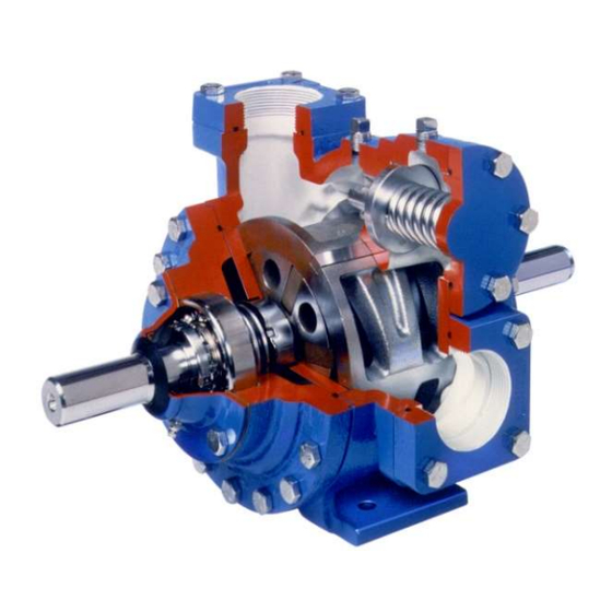
BLACKMER LIQUEFIED GAS PUMPS
FOR LP-GAS AND NH
INSTALLATION OPERATION AND MAINTENANCE INSTRUCTIONS
MODELS: LGLD2E, LGL2E, LGLD3F, LGL3F
and discontinued LGLD3E, LGL3E
TABLE OF CONTENTS
SAFETY DATA ..................................................................... 1
Pump Identification ..................................................... 2
Technical Data ........................................................... 2
Initial Pump Start Up Information ............................... 2
Welded Connections .................................................. 3
Pre-Installation Cleaning ............................................ 3
Location and Piping .................................................... 3
Pump Relief Valve and Bypass Valve ........................ 4
Check Valves ............................................................. 4
Pump Rotation ........................................................... 4
Pump Mounting .......................................................... 4
Coupling Alignment .................................................... 5
V-Belt Drive ................................................................ 5
V-Belt Disassembly .................................................... 5
Pre-Start Up Check List ............................................. 6
Start Up Procedures ................................................... 6
TRUCK MOUNTED PUMPS
Truck Mounting .......................................................... 6
Pump Drive ................................................................ 6
Hydraulic Drive ........................................................... 7
Pre-Start Up Check List ............................................. 7
Start Up Procedures ................................................... 7
Pump Speed .............................................................. 8
Strainers ..................................................................... 8
Lubrication ................................................................. 8
Vane Replacement ..................................................... 9
Pump Disassembly .................................................... 9
Pump Assembly ....................................................... 10
TROUBLE SHOOTING ...................................................... 12
NOTE: Numbers in parentheses following individual parts
indicate reference numbers on Blackmer Parts List 501-C01
Blackmer pump manuals and parts lists may be obtained from
Blackmer's website (www.blackmer.com) or by contacting
Blackmer Customer Service.
SERVICE TRUCK AND BASE MOUNTED
3
Page
960417
INSTRUCTIONS NO. 501-C00
SAFETY DATA
This is a SAFETY ALERT SYMBOL.
When you see this symbol on the product, or in the manual,
look for one of the following signal words and be alert to the
potential for personal injury, death or major property
damage
Warns of hazards that WILL cause serious personal injury,
death or major property damage.
Warns of hazards that CAN cause serious personal injury,
death or major property damage.
Warns of hazards that CAN cause personal injury
or property damage.
NOTICE:
Indicates special instructions which are very
important and must be followed.
NOTICE:
Blackmer liquefied gas pumps MUST only be installed
in systems which have been designed by qualified
engineering personnel. The system MUST conform to
all applicable local and national regulations and safety
standards.
This manual is intended to assist in the installation and
operation of the Blackmer liquefied gas pumps, and
MUST be kept with the pump.
Blackmer liquefied gas pump service shall be
performed by qualified technicians ONLY. Service shall
conform to all applicable local and national regulations
and safety standards.
Thoroughly review this manual, all Instructions and
hazard warnings, BEFORE performing any work on the
Blackmer liquefied gas pumps.
Maintain ALL system and Blackmer liquefied gas pump
operation and hazard warning decals.
Section
501
Effective
Apr 2020
Replaces
Jan 2019
Advertisement
Table of Contents

Related Manuals for BLACKMER LGLD3F


Summarization of Contents
Safety Data
Safety Alerts and Signal Words
Explains the meaning of safety symbols and signal words used in the manual, including DANGER, WARNING, CAUTION, and NOTICE.
Pump Data
Pump Identification Tag
Details the information found on the pump identification tag, including serial and model numbers for reference.
Technical Data
Lists specifications like torque, speed, pressure, and temperature for different pump models.
Initial Pump Start Up Information
Fields to record pump model, serial number, installation date, and initial operating readings.
General Installation and Operation
Installation Notices
Emphasizes installation by qualified personnel and adherence to all applicable regulations and codes.
Welded Connections
Instructions for welding piping with O-rings removed to prevent damage during the process.
Pre-Installation Cleaning
Importance of flushing and cleaning the pump and piping before installation to prevent damage.
Location and Piping
Guidelines for optimal pump placement and piping design to ensure performance and longevity.
Motor Driven Pumps
Pump Relief Valve and Bypass Valve
Explains the function and installation of relief and bypass valves for pump protection and system control.
Check Valves
Discusses the recommendation against check valves in supply tanks for this pump type.
Pump Rotation
How to confirm and change pump rotation for different models based on shaft configuration.
Pump Mounting
Instructions for securely mounting the pump base to a foundation to reduce noise and vibration.
Motor Driven Pumps
Coupling Alignment
Procedures for ensuring proper angular and parallel alignment of couplings between pump and motor.
V-Belt Drive
Detailed steps for installing and adjusting V-belt drives for optimal performance and tension.
V-Belt Disassembly
Procedures for removing V-belt guards, belts, and sheaves for maintenance or replacement.
Motor Driven Pumps
Pre-Start Up Check List
A comprehensive list of essential checks before starting motor-driven pumps.
Start Up Procedures
Step-by-step instructions for safely starting motor-driven pumps, including pressure and flow checks.
LGLD Truck Mounted Pumps
Truck Mounting
Guidelines for securely mounting the pump onto a truck frame or saddle for stable operation.
Pump Drive
Recommendations for power take-off (PTO) drive lines to ensure proper pump operation and minimize wear.
LGLD Truck Mounted Pumps
Hydraulic Drive
Information on driving the pump using hydraulic motors, including adapter and coupling requirements.
Pre-Start Up Check List
Checks required before starting truck-mounted pumps, focusing on piping and pressure gauges.
Start Up Procedures
Steps for starting truck-mounted pumps, including valve operation and pressure checks against relief valves.
Maintenance
Pump Speed
Notes on controlling pump speed for truck-mounted units to prevent exceeding maximum RPM specifications.
Strainers
Importance of regular strainer cleaning to prevent pump starvation and maintain flow.
Lubrication
Procedures and recommendations for lubricating pump bearings and hydraulic motors.
Maintenance
Vane Replacement
Detailed steps for replacing worn vanes in the pump, including proper orientation and installation.
Pump Disassembly
Step-by-step instructions for taking the pump apart, including safety precautions and component removal.
Maintenance
Pump Assembly
Detailed instructions for reassembling the pump, including O-ring and seal installation.
Mechanical Seal Installation
Specific steps for installing rotating and stationary mechanical seal components correctly.
Maintenance
Locknut Adjustment
Procedures for correctly adjusting bearing locknuts to prevent damage and ensure proper bearing operation.
Troubleshooting
Pump Not Priming
Lists probable causes and solutions for the pump failing to prime, such as incorrect rotation or clogged strainers.
Reduced Capacity
Identifies causes and remedies for decreased pump performance, like low speed or excessive restriction.
Troubleshooting
Damaged Vanes
Probable causes for vane damage, including foreign objects or incorrect installation.
Broken Shaft
Probable causes for a broken pump shaft, such as foreign objects or shaft misalignment.
Mechanical Seal Leakage
Potential reasons for mechanical seal leaks, including incompatible O-rings or damaged seal faces.
Overload on Motor
Causes of motor overload, such as insufficient horsepower, misalignment, or improper bearing adjustment.
Need help?
Do you have a question about the LGLD3F and is the answer not in the manual?
Questions and answers