Sign In
Upload
Download
Table of Contents
Contents
Add to my manuals
Delete from my manuals
Share
URL of this page:
HTML Link:
Bookmark this page
Add
Manual will be automatically added to "My Manuals"
Print this page
×
Bookmark added
×
Added to my manuals
Manuals
Brands
ADCMT Manuals
Multimeter
7352E
Operation manual
ADCMT 7352E Operation Manual
Hide thumbs
1
2
3
4
5
6
7
8
9
10
11
12
13
14
15
16
17
18
19
20
21
22
23
24
25
26
27
28
29
30
31
32
33
34
35
36
37
38
39
40
41
42
43
44
45
46
47
48
49
50
51
52
53
54
55
56
57
58
59
60
61
62
63
64
65
66
67
68
69
70
71
72
73
74
75
76
77
78
79
80
81
82
83
84
85
86
87
88
89
90
91
92
93
94
95
96
97
98
99
100
101
102
103
104
105
106
107
108
109
110
111
112
113
114
115
116
117
118
119
120
121
122
123
124
125
126
127
128
129
130
131
132
133
134
135
136
137
138
139
140
141
142
143
144
145
146
147
148
149
150
151
152
153
154
155
156
157
158
159
160
161
162
163
164
165
166
167
168
169
170
171
172
173
174
175
176
177
178
179
180
181
182
183
184
185
186
187
188
189
190
191
192
193
194
195
196
197
198
199
200
201
202
203
204
205
206
207
208
209
210
211
212
213
214
215
216
217
218
page
of
218
Go
/
218
Contents
Table of Contents
Bookmarks
Table of Contents
Table of Contents
List of Illustrations
1 Introduction
Contents of this Manual
Product Overview
2 Precautions
If a Fault Occurs
Removing the Case
Power Fuse
Electromagnetic Interference
Note When Turning on the Power
3 Setup
Inspection on Delivery
Standard Accessories
Installation Environment
Protecting against Electrostatic Discharge
Electrostatic Countermeasures for the Work Floor and Human Body
Electrostatic Countermeasures for the Workbench
ESD Countermeasures
Accessories
Input Cable
Power Requirements
Checking the Power Supply Voltage
Set Power Supply Voltage Indication
Power Supply Voltage
Changing the Power Supply Voltage
Connecting the Power Cable
4 Quick Start
Panel Description
Front Panel Description
Display Section
Power Switch
Measurement Function Keys
Display Section Description
Measurement Range Selection Keys
Sampling Selection Keys
Calculation Selection Keys
MENU/ENTER Key
SHIFT/EXIT/LOCAL Key
Right or Left Display Section Selection Key
Ach Measurement Input Terminals
Bch Measurement Input Terminals
CAT II (Marking)
4.1.2 Rear Panel Description
Rear Panel Description (7352E)
Basic Operation
Measurement Functions
Ach DC Voltage Measurement (DCV-Ach)
Maximum Allowable Applied Voltage (DCV-Ach)
Ach AC Voltage Measurement (ACV-Ach and ACV(AC+DC)-Ach)
DC Voltage Measurement (DCV-Ach)
Measurement Range and Input Impedance (DCV-Ach)
Ach Resistance Measurement (2W-Ach and LP-2W-Ach)
AC Voltage Measurement (ACV-Ach and ACV(AC+DC)-Ach)
Maximum Allowable Applied Voltage (ACV-Ach, ACV(AC+DC)-Ach)
Resistance Measurement (2W-Ach and LP-2W-Ach)
Maximum Allowable Applied Voltage (2W-Ach, LP-2W-Ach)
Ach DC Current Measurement (DCI-Ach)
Maximum Allowable Applied Current and Protection Function (DCI-Ach)
Ach AC Current Measurement (ACI-Ach and ACI(AC+DC)-Ach)
AC Current Measurement (ACI-Ach and ACI(AC+DC)-Ach)
Maximum Allowable Applied Current and Protection Function (ACI-Ach and ACI(AC+DC)-Ach)
Ach Continuity Measurement
Continuity Measurement-Ach
Maximum Allowable Applied Voltage (Continuity-Ach)
Ach Diode Measurement
Diode Measurement-Ach
Maximum Allowable Applied Voltage (Diode-Ach)
Ach Frequency Measurement (FREQ-Ach)
Maximum Allowable Applied Voltage (FREQ-Ach)
Frequency Measurement (FREQ-Ach)
Bch DC Voltage Measurement (DCV-Bch)
Maximum Allowable Applied Voltage (DCV-Bch)
Measurement Range and Input Impedance (DCV-Bch)
Bch DC Current Measurement (DCI-Bch)
Maximum Allowable Applied Current and Protection Function (DCI-Bch)
Bch AC Current Measurement (ACI-Bch and ACI(AC+DC)-Bch)
AC Current Measurement (ACI-Bch and ACI(AC+DC)-Bch)
Maximum Allowable Applied Current and Protection Function (ACI-Bch and ACI(AC+DC)-Bch)
Temperature Measurement
Maximum Allowable Applied Voltage (TEMP)
Setting the Measurement Range
Changing the Measurement Speed and Display Digit
Measurement Speed During the HOLD off (Trigger Source: IMMED)
Measurement Speed During the HOLD on (Trigger Source: EXT) (7352A)
Measurement Speed During the HOLD on (Trigger Source: BUS) GPIB (7352A)/USB
Measurement Speed During the HOLD on (Trigger Source: BUS) RS-232 (7352A)
How to Use Dual Display
Sampling Rate and Display Digits
How to Use Dual Display by Remote Operation
5 Menu Operation and Function Description
Menu
How to Navigate the Menus
Menu Operation
Menu Operation Key and Function
Menu List
Measurement Functions
Continuity Measurement
Temperature Measurement
Measurement Range and Auto-Range
Measurement Function and Range Structure
Auto-Range
Auto-Zero Operation
Auto-Zero
Display Mode Setting
Display Digit Setting
Sampling Operation
Sampling Operations Combining with Function Settings
Single Measurement Sequence
Dual Sequential Measurement Sequence
Dual Synchronous Measurement Sequence
5.8 Trigger Function
Trigger Model
5.8.1 Trigger System Operation
Trigger Source Selection
Trigger Delay (Td)
Trigger Delay Time, Setting Resolution, and Accuracy
Trigger Delay Operation
Calculation Functions
Calculation System Diagram
NULL Calculation
Smoothing Calculation
Scaling Calculation
Db and Dbm Calculations
Comparator Calculation
PASS Condition Setting and PASS/FAIL Judgment
MAX/MIN Calculation
Statistical Calculation
5.9.8 Calculation between 2 Measurements
5.10 Saving and Loading the Measurement Condition Settings
Auto-Loading When Turning on the Power
Saving the Setting Parameters
Loading the Setting Parameters
5.11 Storing and Recalling Measurement Data
Memory Store
Memory Recall
Memory Clear
5.12 System Settings
Disabling Functions
Relationship According to Disabling Function
Front Panel Disabling Function
Error Queue
6 How to Use the Interface
Interface Selection
Gpib (7352A)
Overview
Interface Functions
Precautions in Use of GPIB
Standard Bus Cable
6.2.3 GPIB Setting
Eia-232] (7352A)
Overview
Setting
Output Data Format
Usb
Overview
USB Specifications
Setting up the USB Port
Connecting to a Personal Computer
Usbid Setting
External Trigger Terminal (TRIGGER IN) (7352A)
Simple Equivalent Circuit of Trigger Input Terminal
Command Reference
Selecting the Command Language
Compatibility
6.6.2 Output Data Format
ADC Command Reference
SCPI Command Reference
Status Register Structure
Status Byte Register Structure
Status Byte Register (STB)
Standard Event Status Register (ESR)
Measurement Event Register (MER)
Questionable Event Register (QER)
Operation Event Register (OER)
Sample Programs (GPIB Commands Used in ADC CORPORATION)
Sample Programs (SCPI Commands for GPIB)
Sample Programs (RS-232)
Interface
Sample Programs (USB)
DC Voltage Measurement (DCV)
Ach DC Voltage Measurement (DCV-Ach)
Bch DC Voltage Measurement (DCV-Bch)
AC Voltage Measurement
Ach AC Voltage Measurement (ACV-Ach and ACV(AC+DC)-Ach)
Ach Resistance Measurement (2W-Ach and LP-2W-Ach)
DC Current Measurement (DCI)
Ach DC Current Measurement (DCI-Ach)
Bch DC Current Measurement (DCI-Bch)
AC Current Measurement (ACI, ACI(AC+DC))
Ach AC Current Measurement (ACI-Ach and ACI(AC+DC)-Ach)
Bch AC Current Measurement (ACI-Bch and ACI(AC+DC)-Bch)
Ach Frequency Measurement (FREQ-Ach)
Temperature Measurement (TEMP)
Ach Diode Measurement-Ach
Temperature Measurement
Ach Continuity Measurement-Ach
7.1.10 Calculation Functions
Interface Specifications
General Specifications
Accessories
8 Maintenance
Replacing Fuses
Replacing a Power Fuse
Replacing a Protection Fuse
How to Check Protection Fuses
How to Replace Protection Fuses
Input Terminal Protection Fuse
Cleaning
Cleaning the Outside
Cleaning Others
Calibration
Preparing for Calibration
8.3.2 Calibration Standards
Calibration Point
Calibration Point
8.3.4 Calibration Procedure
Replacing Parts with Limited Life
Parts with Limited Life
Product Disposal and Recycle
Storage
Transportation
Notes Regarding Repair, Replacement, and Periodic Calibration
Before Asking for Repair
Contacting ADC CORPORATION for Repair or Calibration
Address and Phone Number
System Recovery Procedure
Initial Values of Setting Parameters
8.10 Self-Test
Self-Test Items
Display and Key Tests
8.11 Error Message List
7352A Dimensional Outline Drawing
Advertisement
Quick Links
1
Scpi Command Reference
Download this manual
Cover
7352A/E
Digital Multimeter
Operation Manual
FOE-8440254B00
MANUAL NUMBER
Applicable Models
7352A
7352E
First printing August 10, 2007
C
2007
ADC CORPORATION
All rights reserved.
Printed in Japan
Table of
Contents
Previous
Page
Next
Page
1
2
3
4
5
Advertisement
Chapters
Table of Contents
5
List of Illustrations
11
Table of Contents
Need help?
Do you have a question about the 7352E and is the answer not in the manual?
Ask a question
Questions and answers
Related Manuals for ADCMT 7352E
Multimeter ADCMT 7451A Operation Manual
(212 pages)
Multimeter ADCMT 7461A Operation Manual
(212 pages)
Multimeter ADCMT 7461P Operation Manual
(212 pages)
Multimeter ADCMT 7351A Operation Manual
(186 pages)
Multimeter ADCMT 7351E Operation Manual
(186 pages)
Multimeter ADCMT 7352A Operation Manual
(218 pages)
Multimeter ADCMT 7481 Operation Manual
(344 pages)
Summarization of Contents
1. Introduction
1.1 Contents of this Manual
Describes the manual's structure and how to use it for novices and experienced users.
1.2 Product Overview
Provides a summary of the digital multimeter's features and capabilities.
2. Precautions
2.1 If a Fault Occurs
Instructions for immediate actions if smoke, smell, or noise emanates from the instrument.
2.2 Removing the Case
Specifies that only authorized service engineers should open the instrument's case.
2.3 Power Fuse
Explains the function of the power fuse and actions if it blows.
2.4 Electromagnetic Interference
Details potential EMI issues and precautions to prevent them.
3. Setup
3.1 Inspection on Delivery
Procedure for checking the instrument and accessories upon receipt.
3.2 Installation Environment
Specifies the recommended environmental conditions for instrument installation.
3.3 Accessories
Lists and describes the standard and optional accessories for the instrument.
3.4 Power Requirements
Details power supply voltage requirements and connection procedures.
4. Quick Start
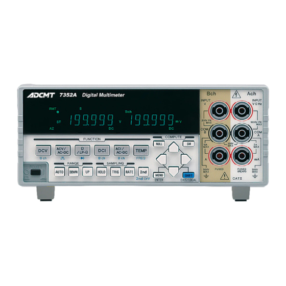
4.1 Panel Description
Overview of the instrument's front and rear panels and their components.
4.2 Basic Operation
Guides through fundamental operations like self-test and basic measurements.
5. Menu Operation and Function Description
5.1 Menu
Explains the layered menu structure and navigation for setting parameters.
5.2 Measurement Functions
Describes parameters within menus for specific measurement functions.
5.3 Measurement Range and Auto-Range
Details measurement range structures and the auto-range function.
5.7 Sampling Operation
Explains the different types of sampling operations available.
5.8 Trigger Function
Covers trigger system operation, source selection, delay, and count settings.
5.9 Calculation Functions
Details the nine available calculation functions like NULL, Scaling, dB, etc.
5.10 Saving and Loading the Measurement Condition Settings
Instructions for saving, loading, and auto-loading measurement parameters.
5.11 Storing and Recalling Measurement Data
Information on how to store and recall measurement data into memory.
5.12 System Settings
Configuration options for system-wide settings like buzzer and function disabling.
6. How to Use the Interface
6.1 Interface Selection
Guidance on selecting and configuring the instrument's interfaces.
6.2 GPIB (7352A)
Overview, precautions, and settings for using the GPIB interface.
6.3 RS-232[EIA-232] (7352A)
Overview, settings, and output data format for the RS-232 interface.
6.4 USB
Details on USB interface overview, specifications, and setup.
6.5 External Trigger Terminal (TRIGGER IN) (7352A)
Information on using the external trigger input for instrument control.
6.6 Command Reference
Reference for ADC and SCPI commands for instrument control.
6.7 Sample Programs
Example programs for controlling the instrument via GPIB, RS-232, and USB.
7. Specifications
7.1 Specifications
Detailed specifications for the instrument's performance and accuracy.
7.2 Interface Specifications
Technical details for the instrument's remote control interfaces.
7.3 General Specifications
General operating conditions, power, dimensions, safety, and EMC compliance.
7.4 Accessories
List of standard and optional accessories available for the instrument.
8. Maintenance
8.1 Replacing Fuses
Instructions for safely replacing power and protection fuses.
8.2 Cleaning
Procedures and precautions for cleaning the instrument's exterior and parts.
8.3 Calibration
Guidance on how to perform calibration to maintain measurement accuracy.
8.4 Replacing Parts with Limited Life
Information on parts with limited lifespan and recommended replacement.
8.5 Product Disposal and Recycle
Guidelines for proper disposal and recycling of instrument components.
8.6 Storage
Recommendations for storing the instrument when not in use.
8.7 Transportation
Instructions for safely packing and transporting the instrument.
8.8 Notes Regarding Repair, Replacement, and Periodic Calibration
Troubleshooting advice before requesting repair or calibration.
8.9 System Recovery Procedure
Steps for initializing instrument settings to factory defaults or shipping values.
8.10 Self-Test
Procedures for performing self-tests on the instrument's hardware and software.
8.11 Error Message List
A comprehensive list of error codes, descriptions, and solutions.
Table of Contents
Print
Rename the bookmark
Delete bookmark?
Delete from my manuals?
Login
Sign In
OR
Sign in with Facebook
Sign in with Google
Upload manual
Upload from disk
Upload from URL
Need help?
Do you have a question about the 7352E and is the answer not in the manual?
Questions and answers