
Related Manuals for ADCMT 7461A


Summarization of Contents
1. INTRODUCTION
1.1 Contents of this Manual
Describes the contents of this manual and the product overview.
2. PRECAUTIONS
2.1 If a Fault Occurs
Instructs to disconnect power if smoke, smell, or noise emanates from the instrument.
2.2 Removing the Case
States that the instrument case should only be opened by service engineers.
2.3 Power Fuse
Explains the function of the power fuse and actions if it blows.
2.4 Electromagnetic Interference
Discusses potential interference and methods to prevent it.
2.5 Note When Turning on the Power
Advises not to connect DUTs when turning on the power.
3. SETUP
3.1 Inspection on Delivery
Details procedures for checking the product and accessories after receiving it.
3.2 Installation Environment
Describes the environmental conditions required for installing the instrument.
3.3 Accessories
Lists and describes the accessories included with the instrument.
3.4 Power Requirements
Explains power requirements and how to connect the power cable.
4. QUICK START
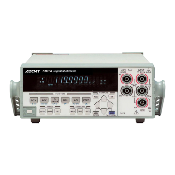
4.1 Panel Description
Describes the front and rear panels of the instrument, including their sections and controls.
4.2 Basic Operation
Covers initial operations like self-test, measurement sequences, and basic settings.
5. MENU OPERATION AND FUNCTION DESCRIPTION
5.1 Menu
Explains the layered menu structure and how to navigate through it.
5.2 Measurement Functions and Parameters
Details the instrument's measurement functions and their associated parameters.
5.3 Measurement Range and Auto-Range
Explains how to set measurement ranges and use the auto-range feature.
5.4 Auto-Zero Operation
Describes the auto-zero function to eliminate offset errors.
5.5 Display Mode Setting
Explains how to set the display mode to ON or OFF.
5.6 Display Digit Setting
Describes how to set the number of display digits.
5.7 Sampling Operation
Explains the instrument's measurement sequence and sampling process.
5.7.1 Sampling Interval (SI) and Integration Time (IT) Settings
Details how to set sampling interval and integration time.
5.7.2 Sampling Count Setting
Explains how to set the number of samples taken per trigger.
5.8 Trigger Function
Describes the trigger system, including detection, delay, and multiple sampling.
5.8.2 Trigger Source Selection
Explains how to select the trigger source for measurements.
5.8.3 Trigger Delay (Td)
Details how to set the trigger delay time.
5.8.4 Trigger Count Setting
Explains how to set the trigger count.
5.8.5 Level Trigger and Delta Trigger
Describes how to acquire data by detecting input signal changes using Level or Delta triggers.
5.9 Calculation Functions
Lists and describes the instrument's eight calculation functions.
5.9.1 NULL Calculation
Explains how the NULL calculation subtracts a fixed value from the measurement.
5.9.2 Smoothing Calculation
Describes the smoothing function for reducing noise via moving averaging.
5.9.3 Scaling Calculation
Explains the scaling calculation and how to set its constants.
5.9.4 dB and dBm calculation
Details the dB and dBm calculations for decibel conversion.
5.9.5 Comparator Calculation
Explains the comparator function for setting HI/GO/LO judgment conditions.
5.9.6 MAX/MIN Calculation
Describes how to calculate and display maximum, minimum, and average values.
5.9.7 Statistical Calculation
Explains how to calculate statistical values like mean, std dev, and dispersion.
5.10 Saving and Loading the Measurement Condition Settings
Covers saving and loading instrument settings into memory.
5.11 Storing and Recalling the Measurement Data
Explains how to store and recall measurement data in the instrument's memory.
5.12 System Settings
Covers various system settings like buzzer, input terminals, and function disabling.
5.12.4 Front Panel Disabling Function
Explains how to disable all front panel keys using a password.
5.12.5 Error Queue
Describes how to read and clear the instrument's error queue.
6. HOW TO USE THE INTERFACE
6.1 Interface Selection
Explains how to select and set the communication interface (GPIB or USB).
6.2 GPIB
Provides an overview of the GPIB interface, its general specifications, and functions.
6.3 USB
Details the USB interface, its specifications, and setup procedures.
6.4 Control Signal
Explains control signals like external trigger input and complete signal output.
6.5 Comparator Output
Describes the comparator output signals (TTL and optical relay) and their specifications.
6.6 Digital Output (7461P Only)
Explains the digital output functionality specific to the 7461P model.
6.7 Command Reference
Provides reference information for ADC and SCPI commands.
6.7.2 Output Data Format
Details the format of measurement data output with and without headers.
6.7.3 ADC Command Reference
Lists and describes the ADC commands for instrument control.
6.7.4 SCPI Command Reference
Provides reference for SCPI commands, including syntax and parameters.
6.7.5 Status Register Structure
Explains the layered status register structure and event allocation.
6.8 Sample Programs (Command used in ADC CORPORATION)
Provides sample programs for controlling the instrument via GPIB using ADC commands.
6.9 Sample Programs (SCPI command)
Provides sample programs for controlling the instrument via GPIB using SCPI commands.
7. SPECIFICATIONS
7.1 Specifications
Provides detailed specifications for measurement functions, accuracy, and conditions.
7.1.1 DC Voltage Measurement (DCV)
Details specifications for DC Voltage Measurement, including ranges, accuracy, and noise rejection.
7.1.2 AC Voltage Measurement (ACV, ACV(AC+DC))
Details specifications for AC Voltage Measurement, including accuracy and frequency response.
7.1.3 Resistance Measurement (2W, LP-2W, 4W, LP-4W)
Provides specifications for Resistance Measurement across various modes.
7.1.4 DC Current Measurement (DCI)
Details specifications for DC Current Measurement, including ranges and accuracy.
7.1.5 AC Current Measurement (ACI, ACI(AC+DC))
Details specifications for AC Current Measurement, including accuracy and crest factor.
7.1.6 Frequency Measurement (FREQ)
Provides specifications for Frequency Measurement, including accuracy and bandwidth.
7.1.7 Diode Measurement
Details specifications for Diode Measurement.
7.1.8 Continuity Measurement
Provides specifications for Continuity Measurement.
7.1.9 Temperature Measurement (TEMP-2W, TEMP-3W, TEMP-4W)
Details specifications for Temperature Measurement using various wire configurations.
7.1.10 Measurement Time and Display Digits
Specifies measurement speeds, conditions, and display digit capabilities.
7.1.11 Calculation Functions
Describes the mathematical operations and display values for calculation functions.
7.2 Interface Specifications
Lists the technical specifications for the GPIB, USB, and comparator interfaces.
7.3 General Specifications
Provides general specifications including operating environment, dimensions, and safety.
7.4 Options
Lists available options for the instrument.
8. MAINTENANCE
8.1 Replacing Fuses
Provides instructions and fuse specifications for replacement.
8.2 Cleaning
Describes the procedures and warnings for cleaning the instrument.
8.3 Calibration
Explains the process and standards for instrument calibration.
8.3.4 Calibration Procedure
Details the step-by-step procedure for calibrating the instrument.
8.4 Replacing Parts with Limited Life
Lists parts with limited lifespan and their expected service life.
8.5 Product Disposal and Recycle
Provides guidelines for environmentally responsible disposal and recycling of the product.
8.6 Storage
Gives instructions for storing the instrument when not in use.
8.7 Transportation
Provides guidelines for safely transporting the instrument.
8.8 Notes Regarding Repair, Replacement, and Periodic Calibration
Provides important notes before contacting for service or calibration.
8.9 System Recovery Procedure
Explains how to initialize settings and recover system parameters.
8.10 Self-Test
Describes how to perform self-tests on the instrument's hardware and software.
8.11 Error Message List
Lists potential error messages and provides solutions for troubleshooting.
Need help?
Do you have a question about the 7461A and is the answer not in the manual?
Questions and answers