Sign In
Upload
Download
Table of Contents
Contents
Add to my manuals
Delete from my manuals
Share
URL of this page:
HTML Link:
Bookmark this page
Add
Manual will be automatically added to "My Manuals"
Print this page
×
Bookmark added
×
Added to my manuals
Manuals
Brands
ADCMT Manuals
Multimeter
7351A
Operation manual
ADCMT 7351A Operation Manual
Hide thumbs
1
2
Table Of Contents
3
4
5
6
7
8
9
10
11
12
13
14
15
16
17
18
19
20
21
22
23
24
25
26
27
28
29
30
31
32
33
34
35
36
37
38
39
40
41
42
43
44
45
46
47
48
49
50
51
52
53
54
55
56
57
58
59
60
61
62
63
64
65
66
67
68
69
70
71
72
73
74
75
76
77
78
79
80
81
82
83
84
85
86
87
88
89
90
91
92
93
94
95
96
97
98
99
100
101
102
103
104
105
106
107
108
109
110
111
112
113
114
115
116
117
118
119
120
121
122
123
124
125
126
127
128
129
130
131
132
133
134
135
136
137
138
139
140
141
142
143
144
145
146
147
148
149
150
151
152
153
154
155
156
157
158
159
160
161
162
163
164
165
166
167
168
169
170
171
172
173
174
175
176
177
178
179
180
181
182
183
184
185
186
page
of
186
Go
/
186
Contents
Table of Contents
Bookmarks
Table of Contents
Table of Contents
1 Introduction
Contents of this Manual
Product Overview
2 Precautions
If a Fault Occurs
Removing the Case
Power Fuse
Electromagnetic Interference
Note When Turning on the Power
3 Setup
Inspection on Delivery
Standard Accessories
Installation Environment
Protecting against Electrostatic Discharge
Electrostatic Countermeasures for the Work Floor and Human Body
Electrostatic Countermeasures for the Workbench
ESD Countermeasures
Accessories
Input Cable
Caution When Connecting Peripherals
Power Requirements
Checking the Power Supply Voltage
Indication of the Set Power Supply Voltage
Relation Table between AC Power Supply Voltage and Indication of Set Power Supply Voltage
Changing the Power Supply Voltage
Connecting the Power Cable
Selecting the Power Supply Frequency
4 Quick Start
Panel Description
Front Panel Description
Display Section
Power Switch
Measurement Function Keys
Display Section Description
Measurement Range Selection Keys
Sampling Selection Keys
Calculation Selection Keys
MENU/ENTER Key
SHIFT/EXIT/LOCAL Key
Front Input Section for Measurement
CAT II (Marking)
Rear Panel Description
Rear Panel Description (7351A)
Rear Panel Description (7351E + Option 03)
Basic Operation
Measurement Functions
DC Voltage Measurement (DCV)
Maximum Allowable Applied Voltage (DCV)
AC Voltage Measurement (ACV and ACV(AC+DC))
Measurement Range and Input Impedance (DCV)
Maximum Allowable Applied Voltage (ACV and ACV (AC+DC))
Resistance Measurement (2W and LP-2W)
AC Voltage Measurement (ACV and ACV (AC+DC))
Maximum Allowable Applied Voltage (2W and LP-2W)
DC Current Measurement (DCI)
Maximum Allowable Applied Current and Protection Function (DCI)
AC Current Measurement (ACI and ACI (AC+DC))
Maximum Allowable Applied Current and Protection Function (ACI and ACI (AC+DC))
Continuity Measurement
AC Current Measurement (ACI and ACI (AC+DC))
Diode Measurement
Maximum Allowable Applied Voltage (Continuity)
Maximum Allowable Applied Voltage (Diode)
Frequency Measurement (FREQ)
Maximum Allowable Applied Voltage (FREQ)
Setting the Measurement Range
Changing the Measurement Speed and Display Digit
Measurement Speed (A) When in the HOLD off (Trigger Source: IMMED)
Measurement Speed (B) When in the HOLD on (Trigger Source: EXT)
Measurement Speed (B) When in the HOLD on (Trigger Source: BUS)
Measurement Speed (B) When in the HOLD on (Trigger Source: BUS
Sampling Rate and Display Digits
5 Menu Operation and Function Description
Menu
How to Navigate the Menus
Menu Operation
Menu Operation Key and Function
Menu List
Measurement Functions
Continuity Measurement
Measurement Range and Auto-Range
Measurement Function and Range Structure
Auto-Range
Auto-Zero Operation
Display Mode Setting
Display Digit Setting
Measurement Sequence
Trigger Function
Trigger Model
Trigger System Operation
Trigger Source Selection
Trigger Delay (Td)
Trigger Delay Time, Setting Resolution, and Accuracy
Calculation Functions
Calculation System Diagram
NULL Calculation
Smoothing Calculation
Scaling Calculation
Db and Dbm Calculation
Comparator Calculation
MAX/MIN Calculation
5.9.7 Statistical Calculation
5.10 Saving and Loading the Measurement Condition Settings
Auto-Loading When Turning on the Power
Saving the Setting Parameters
Loading the Setting Parameters
5.11 Storing and Recalling the Measurement Data
Memory Store
Memory Recall
Memory Clear
5.12 System Settings
Power Supply Frequency
Disabling Functions
Relationship According to Disabling the Function
Front Panel Disabling Function
Error Queue
6 How to Use the Interface
Interface Selection
Response to the *IDN? Command
Gpib (7351A)
Overview
Interface Functions
6.2.2 Precautions in Use of GPIB
Standard Bus Cable
GPIB Setting
EIA-232] (7351E + Option 03)
Overview
Setting
Output Data Format
Sample Program (RS-232)
Usb
Overview
USB Specifications
Setting up the USB Port
Connecting to a Personal Computer
Usbid Setting
Control Signal (7351A, 7351E + Option 03)
External Trigger Terminal (TRIGGER IN)
Simple Equivalent Circuit of Trigger Input Terminal
Measurement Complete Signal Terminal (COMPLETE OUT)
Simple Equivalent Circuit of Complete Signal Output Terminal
Comparator Output (7351E + Option 03)
Signal Output Pin
Optical Semiconductor Relay Contact and TTL Logical Output (A)
Optical Semiconductor Relay Contact and TTL Logical Output (B)
Command Reference
Selecting the Command Language
Compatibility
Output Data Format
ADC Command Reference
SCPI Command Reference
Status Register Structure
6.7.5 Status Register Structure
Status Byte Register Structure
Status Byte Register (STB)
Standard Event Status Register (SESR)
Measurement Event Register (MER)
Questionable Event Register (QER)
Operation Event Register (OER)
Sample Programs (Command Used in ADC CORPORATION)
Sample Programs (SCPI Command)
7 Specifications
DC Voltage Measurement (DCV)
AC Voltage Measurement (ACV, ACV(AC+DC))
Resistance Measurement (2W, LP-2W)
DC Current Measurement (DCI)
AC Current Measurement (ACI, ACI(AC+DC))
Frequency Measurement (FREQ)
Continuity Measurement
Diode Measurement
Measurement Time and Display Digits
7.1.10 Calculation Functions
Interface Specifications
General Specifications
8 Maintenance
Replacing Fuses
Replacing a Power Fuse
Replacing a Protection Fuse
How to Check Protection Fuses
How to Replace Protection Fuses
Input Terminal Protection Fuse
Cleaning
Cleaning the Outside
Cleaning Others
Calibration
Preparing for Calibration
Calibration Standards
Calibration Point
Calibration Point
Calibration Procedure
Replacing Parts with Limited Life
Parts with Limited Life
Product Disposal and Recycle
Storage
Transportation
Notes Regarding Repair, Replacement, and Periodic Calibration
Before Asking for Repair
Contacting ADC CORPORATION for Repair or Calibration
Address and Phone Number
System Recovery Procedure
Initial Values of Setting Parameters
8.10 Self-Test
Display and Key Tests
Self-Test Items
8.11 Error Message List
Dimensional Outline Drawing
Alphabetical Index
Advertisement
Quick Links
Download this manual
Cover
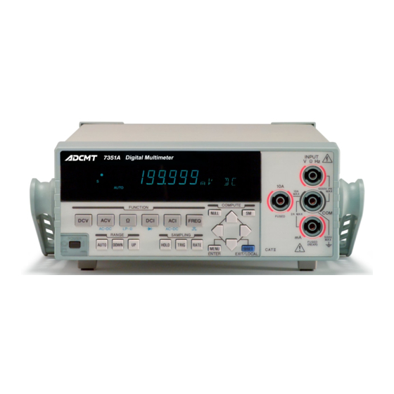
7351A/E
Digital Multimeter
Operation Manual
FOE-8440238F00
MANUAL NUMBER
Applicable Models
7351A
7351E
First printing March 30, 2007
C
2007
ADC CORPORATION
All rights reserved.
Printed in Japan
Table of
Contents
Previous
Page
Next
Page
1
2
3
4
5
Advertisement
Table of Contents
Need help?
Do you have a question about the 7351A and is the answer not in the manual?
Ask a question
Questions and answers
Related Manuals for ADCMT 7351A
Multimeter ADCMT 7451A Operation Manual
(212 pages)
Multimeter ADCMT 7461A Operation Manual
(212 pages)
Multimeter ADCMT 7461P Operation Manual
(212 pages)
Multimeter ADCMT 7351E Operation Manual
(186 pages)
Multimeter ADCMT 7352A Operation Manual
(218 pages)
Multimeter ADCMT 7352E Operation Manual
(218 pages)
Multimeter ADCMT 7481 Operation Manual
(344 pages)
This manual is also suitable for:
7351e
Table of Contents
Save PDF
Print
Rename the bookmark
Delete bookmark?
Delete from my manuals?
Login
Sign In
OR
Sign in with Facebook
Sign in with Google
Upload manual
Upload from disk
Upload from URL


Need help?
Do you have a question about the 7351A and is the answer not in the manual?
Questions and answers