
Related Manuals for ADCMT 7461P


Summarization of Contents
INTRODUCTION
Contents of this Manual
Describes the structure and content of the operation manual.
Product Overview
Provides a summary of the digital multimeter's main features and capabilities.
PRECAUTIONS
If a Fault Occurs
Instructs on immediate actions in case of instrument malfunction or abnormal emissions.
Removing the Case
Specifies that only authorized service personnel should open the instrument case.
Power Fuse
Explains the role of the power fuse in protecting the instrument from overcurrent.
Electromagnetic Interference
Details potential EMI and methods to prevent interference with other electronic devices.
Note When Turning on the Power
Advises against connecting DUTs (Device Under Test) when powering on the instrument.
SETUP
Inspection on Delivery
Guides users on checking the instrument and accessories for damage upon receipt.
Installation Environment
Specifies the recommended environmental conditions for instrument installation and operation.
Accessories
Lists and describes the standard accessories included with the instrument.
Power Requirements
Details the power specifications and connection procedures for the instrument.
QUICK START
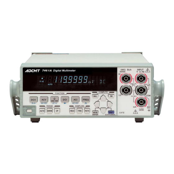
Panel Description
Describes the functions of the front and rear panel controls and connectors.
Basic Operation
Outlines the fundamental steps for operating the instrument after initial setup.
MENU OPERATION AND FUNCTION DESCRIPTION
Menu Structure and Navigation
Explains the layered menu structure and how to navigate through settings.
Measurement Functions and Parameters
Details various measurement functions and their configurable parameters.
Measurement Range and Auto-Range
Describes how to select measurement ranges and utilize the auto-ranging feature.
Auto-Zero Operation
Explains the auto-zero function for eliminating offset errors in measurements.
Sampling Operation
Covers settings and procedures for sampling data during measurements.
Trigger Function
Details the instrument's trigger system for controlling measurement initiation.
Calculation Functions
Describes various calculation functions like NULL, Scaling, dB, Statistics, etc.
Saving and Loading Settings
Explains how to save and load instrument settings for future use.
Storing and Recalling Measurement Data
Describes the process of storing and retrieving measurement data in memory.
System Settings
Covers system-level configurations like buzzer, input terminals, and disabling functions.
HOW TO USE THE INTERFACE
Interface Selection
Guides on selecting and configuring the GPIB or USB interface for remote control.
GPIB Communication
Details the GPIB interface, its functions, settings, and precautions for use.
USB Communication
Explains the USB interface, its specifications, and setup procedures for computer connection.
Control Signals
Describes external trigger input and complete signal output terminals.
Comparator and Digital Output
Details the comparator output signals and digital output capabilities for the 7461P.
Command Reference
Provides a comprehensive reference for SCPI and ADC commands for instrument control.
SPECIFICATIONS
General Specifications
Lists general operating, storage, and physical specifications of the instrument.
DC Voltage Measurement (DCV) Specifications
Details accuracy, input impedance, and allowable voltage for DCV measurements.
AC Voltage Measurement (ACV, ACV(AC+DC)) Specifications
Covers accuracy, input impedance, and allowable voltage for ACV measurements.
Resistance Measurement Specifications
Provides accuracy and technical details for 2W, LP-2W, 4W, and LP-4W resistance measurements.
DC Current Measurement (DCI) Specifications
Details accuracy, input terminals, and allowable current for DCI measurements.
AC Current Measurement (ACI, ACI(AC+DC)) Specifications
Lists accuracy and technical details for ACI and ACI(AC+DC) current measurements.
Frequency Measurement (FREQ) Specifications
Specifies accuracy, bandwidth, and input signal requirements for frequency measurements.
Diode Measurement Specifications
Outlines measurement current and accuracy for diode measurements.
Continuity Measurement Specifications
Details measurement current and judgment range for continuity tests.
Temperature Measurement Specifications
Covers measurement range, wire connection, and units for temperature measurements.
Measurement Time and Display Digits
Details measurement speed, sampling intervals, and display digit configurations.
Calculation Functions Specifications
Summarizes the display values and formulas for various calculation functions.
Interface Specifications
Lists the technical specifications for the remote control, USB, and GPIB interfaces.
Options
Lists available optional accessories and configurations for the instrument.
MAINTENANCE
Replacing Fuses
Provides instructions and safety precautions for replacing power and protection fuses.
Cleaning
Describes the procedures for cleaning the instrument and important safety warnings.
Calibration
Details the process for calibrating the instrument to maintain measurement accuracy.
Replacing Parts with Limited Life
Lists components with limited lifespan and their expected operational life.
Product Disposal and Recycle
Provides guidelines for environmentally responsible disposal and recycling of the product.
Storage
Recommends proper storage conditions for the instrument when not in use.
Transportation
Outlines the procedure for safely packing and transporting the instrument.
Notes on Repair and Calibration
Advises on information needed when contacting for repair or calibration services.
System Recovery Procedure
Explains how to initialize and restore instrument settings to default or shipping values.
Self-Test
Describes how to perform self-tests on the instrument's hardware and software components.
Display and Key Tests
Guides on testing the instrument's display segments and front panel keys.
Error Message List
Lists instrument error codes, descriptions, and recommended solutions.
Need help?
Do you have a question about the 7461P and is the answer not in the manual?
Questions and answers