Table of Contents
Advertisement
Quick Links
AnoFrame VersaMount
Parts
AnoFrame
AnoFrame
Rails
Split Rails
Instructions For Assembly
Step 1
Locate the two split rails and the solid
rail that is the same length as the split
rails.
Insert two corner brackets into each
end of the solid side Ano rail. Insert
one corner bracket into each end of
each split side Ano rail. Fig. 2
Note: Tension tabs on corner
brackets face towards outside of
frame. Fig. 1
Step 2
For ceiling application, slide screw
tabs into channel of top Ano rail. For
wall applications, slide into side Ano
rail. Fig. 3
Step 3
Place one transitional collar over each
screw tab and push onto frame. Fig. 4.
Step 4
Finish assembling frame following the
sequence in Fig. 5.
Note: Placement of split rails will
depend on type of frame. Split rails
will be on the top for top-loading
frames and on the side for side-
loading frames.
The AnoFrame VersaMount is a trademark of Rose Displays, Ltd. Neither
the manufacturer nor any sales agent may be held liable for injury, loss
or damage resulting from the use of these products.
Part #02INSVersaMountScrewBaseSide
Incept-9.6.02
TM
Screw Base
Instruction Sheet (page 1 of 2)
Screw Tabs
Corner
Transitional
Brackets
Collars
Figure 3
Posts
Figure 1
solid rail
solid rail
Figure 5
Tel# 1-800-631-9707 Fax# 1-800-560-2890
#97-0451R
Screw
Bases
Wood Screws
or Togglebolts
Screws
Figure 2
Figure 4
35 Congress Street, Salem MA 01970
e-mail:signware@rosedisplays.com
Advertisement
Table of Contents

Related Manuals for ROSE DISPLAYS ANOFRAME VERSAMOUNT SCREW BASE SIDE LOAD


Summary of Contents for ROSE DISPLAYS ANOFRAME VERSAMOUNT SCREW BASE SIDE LOAD
- Page 1 The AnoFrame VersaMount is a trademark of Rose Displays, Ltd. Neither the manufacturer nor any sales agent may be held liable for injury, loss or damage resulting from the use of these products.
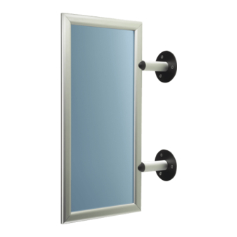
- Page 2 Fig. 10 Figure Finished Look The AnoFrame VersaMount is a trademark of Rose Displays, Ltd. Neither the manufacturer nor any sales agent may be held liable for injury, loss or damage resulting from the use of these products. Part #02INSVersaMountScrewBaseSide...
- Page 3 The AnoFrame VersaMount is a trademark of Rose Displays, Ltd. Neither the manufacturer nor any sales agent may be held liable for injury, loss or damage resulting from the use of these products.
- Page 4 Fig. 10 Figure Finished Look The AnoFrame VersaMount is a trademark of Rose Displays, Ltd. Neither the manufacturer nor any sales agent may be held liable for injury, loss or damage resulting from the use of these products. Part #02INSVersaMountScrewBaseSide...
Need help?
Do you have a question about the ANOFRAME VERSAMOUNT SCREW BASE SIDE LOAD and is the answer not in the manual?
Questions and answers