Table of Contents
Advertisement
Bike-Lift Europe s.r.l.
via Don Milani, 40/42
43012 Sanguinaro di Fontanellato (PARMA) – Italy
Website: www.bikelifteurope.it
E-mail: info@bikelifteurope.it
Operating manual number 057-2-6-0001-R0
Version 2021
European Communities
Use and Maintenance Manual
Scissor lifting platform
Master 504 Gate
Model
MA504-002
MA504-003
MA504-004
MAX 516 Gate
Model
MG516-001
MG516-002
MG516-003
MG516-004
MAX 516
Model
M516-001
M516-002
M516-003
M516-004/R
SPORT 500
Model
SG500-001
SG500-002
SG500-003
SG500-004/R
Version
COMPRESSED AIR PUMP
ELECTRO-HYDRAULIC PUMP
ELECTRONIC WITH REMOTE
CONTROL
Version
FOOT PUMP
COMPRESSED AIR PUMP
ELECTRO-HYDRAULIC PUMP
ELECTRONIC WITH REMOTE
CONTROL
Version
FOOT PUMP
COMPRESSED AIR PUMP
ELECTRO-HYDRAULIC PUMP
ELECTRONIC WITH REMOTE
CONTROL
Version
FOOT PUMP
COMPRESSED AIR PUMP
ELECTRO-HYDRAULIC PUMP
ELECTRONIC WITH REMOTE
CONTROL
EN
Page 1
Advertisement
Table of Contents

Related Manuals for Bike-Lift MAX 516


Summary of Contents for Bike-Lift MAX 516
- Page 1 European Communities Use and Maintenance Manual Scissor lifting platform Master 504 Gate Model Version MA504-002 COMPRESSED AIR PUMP ELECTRO-HYDRAULIC PUMP MA504-003 MA504-004 ELECTRONIC WITH REMOTE CONTROL MAX 516 Gate Model Version MG516-001 FOOT PUMP ...
-
Page 2: Table Of Contents
Summary Information section ........................4 Preface ..............................4 Prohibitions ............................5 Warranty ............................. 5 Warranty conditions ........................5 Insurance ............................5 Manufacturer identification ........................ 6 Technical assistance and spare parts ....................6 EC Declaration of conformity ......................7 Normative references ......................... 8 Legend key ............................ - Page 3 Installation section ........................24 Power ............................ 24 Commissioning ........................25 Dismantling/scrapping section ....................26 Dismantling ..........................26 Mechanical dismantling ......................26 Scrapping ..........................26 7. Operation section ........................27 Loading operations ........................ 27 Unloading operations ......................28 Lifting types ........................... 28 7.3.1.
-
Page 4: Information Section
Drawings, data and specifications contained in this Manual can be modified at any time by the company, without prior notice. In case of significant changes of the machine due to the installation of new parts, Bike-Lift Europe s.r.l. will compile an updated Manual which will be sent to the Customer together with the purchased part. -
Page 5: Prohibitions
It also becomes void if the product has been submitted to performances exceeding those indicated by Bike-Lift Europe s.r.l. 1.3.2 Insurance All Bike-Lift products are insured with a Recurring Card Payment (RCP) policy with a price ceiling of €3,000,000. Damages caused by negligence or tampering are excluded. Operating manual number 057-2-6-0001-R0... -
Page 6: Manufacturer Identification
CAUTION: THE RECIPIENT WILL BE CHARGED FOR THE REPLACEMENT TOGETHER WITH THE SHIPPING COSTS. We recommend that you always contact Bike-Lift Europe s.r.l. for all those assistance and maintenance operations which are not described or indicated in this Manual. Operating manual number 057-2-6-0001-R0... -
Page 7: Ec Declaration Of Conformity
EC Declaration of conformity (Annex II, part 1, section A of directive 2006/42/EC) Manufacturer: Company: Bike-Lift EUROPE S.r.l. Address: Via Don Milani, 40/42 - 43012 Sanguinaro di Fontanellato (PR) - Italy Declares under its sole responsibility that the machines: MAX 516//MAX 516 GATE/MASTER 506 GATE/SPORT 500 GATE... -
Page 8: Normative References
Normative references The machine is identified by the European Communities (CE) marking drawn up according to the specifications of the Machinery Directive 2006/42/EC and subsequent updates. Reference Title 2006/42/EC Machinery Safety Directive 2014/30/EC Electromagnetic Compatibility Directive (EMC) 2014/35/EU Low-Voltage Directive (LVD) Safety of machinery - General principles of design - Risk EN ISO 12100 (2010) Assessment and risk reduction... -
Page 9: Legend Key
Legend key LIFTING PLATFORM: hydraulic/electric/pneumatic scissor handling system for the maintenance and repair of motorcycles and scooters. The specific identification of the lifting platform is indicated on the cover. OPERATOR: In compliance with Directive 2006/42/EC and subsequent updates, it is specified that the term ‘operator’... -
Page 10: 2-Machine Description
2.1 Machine name Scissor lifting platform for the maintenance and repair of motorcycles and scooters with a maximum capacity of 500 kg. The handling of the Bike-Lift lifting platforms can be done through one of the following systems: hydraulic pedal system;... -
Page 11: Machine Description
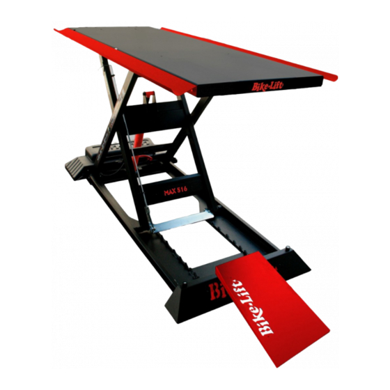
Machine description The machine known as Motorbike Lifting Platform is a suitable equipment to support motorcycles during the maintenance and repair phase in a comfortable and safe way. The basic parts of the lifting platform (see Figure 2) are: Figure 2 – Model of a lifting platform an elevating work platform (red);... -
Page 12: Intended Use
2.4 Intended use Disseminate the instructions described in this chapter to all personnel involved in the preparation and use of the machine. The machine is intended for lifting motorcycles for maintenance purposes. The machine has been designed and built for the specified use; a different use and non-compliance with the technical parameters set by the Manufacturer may be dangerous for the operators. -
Page 13: Technical Specifications
2.5 Technical specifications 2.5.1 MASTER 506 GATE (see exploded diagram attached to this Manual) VERTICAL SCISSOR LIFTING PLATFORM - MASTER 506 GATE PARAMETER VALUE Maximum load capacity 500 kg Maximum height 130 cm Minimum height 19 cm Safety locking positions Lifting tabletop size 220x75 cm Side wings size... -
Page 14: Max 516 Gate
2.5.2 MAX 516 GATE (see exploded diagram attached to this Manual) VERTICAL SCISSOR LIFTING PLATFORM – MAX 516 GATE PARAMETER VALUE Maximum bearing 500 kg Maximum height 120 cm Minimum height 19 cm Safety positions number Lifting surface size 210x75 cm Side wings size 210x12 cm Total space of the lifting platform... -
Page 15: Max 516
2.5.3 MAX 516 (see exploded diagram attached to this Manual) VERTICAL SCISSOR LIFTING PLATFORM – MAX 516 PARAMETER VALUE Maximum bearing 500 kg Maximum height 120 cm Minimum height 19 cm Safety positions number Lifting surface size 210x75 cm Side wings size 210x12 cm Total space of the lifting platform 210x99 cm... -
Page 16: Sport 500
2.5.4 SPORT 500 (see exploded diagram attached to this Manual) VERTICAL SCISSOR LIFTING PLATFORM – SPORT 500 PARAMETER VALUE Maximum bearing 500 kg Maximum height 120 cm Minimum height 19 cm Safety positions number Lifting surface size 210x60 cm Side wings size 210x12 cm Total space of the lifting 210x84 cm... -
Page 17: Safety Section
Safety section Environmental working values The use environment of the machine must be well lit, must not present explosion hazards of any kind and must be protected from atmospheric precipitations. The machine works properly within the following values: Ambient temperature between 5° and 40° C; ... -
Page 18: Operator Protections
Finally, we remind you that the handling, installation, use, maintenance and putting out of service of the machine represent a source of danger if these operations are not performed in compliance with the requirements of this Manual or without the necessary caution and attention required. - Page 19 blanked. Operating manual number 057-2-6-0001-R0 Page 19 Version 2021...
-
Page 20: Pictograms
ALWAYS keep the mechanical lock hooked during work, in order to weigh down the weight of the structure and of the vehicle standing on it even on the toothed bars at the base. During the use of the lifting platform it is very important to pay the utmost attention to the ascent and descent manoeuvres. -
Page 21: Additional Safety Systems For The Built-In Version
Additional safety systems for the built-in version For the built-in version, the lifting platform presents risks of crushing and getting stuck inside the housing. During the ascent/descent phase the operator is required to distance from the lifting platform according to the length allowed by the control panel cable. -
Page 22: Transport And Handling Section
Transport and handling section Transport, handling and storage CAUTION: Disseminate the instructions described in this chapter to all personnel involved in the Transport and handling of the machine. For safety reasons, the moving parts must be locked before Transport. Packaging and Transport The machine is packed for Transport directly from the Manufacturer. -
Page 23: Receipt And Check
It is recommended that the unloading or handling operations to be carried out with a forklift truck by a single Operator equipped with workshop gloves, safety footwear and protective helmet, as required by current regulations. This operator must pay maximum attention to all Transport phases. Do not allow any other person to stand in the operation area of the forklift truck in order to prevent the accidental fall of the boxes. -
Page 24: Installation Section
Installation section The machine must be installed in compliance with the safety regulations and instructions included in this chapter. CAUTION: COMPLETELY remove the wooden sleepers located under the lifting platform by removing the fixing screws before using the machine. The machine does not need a basis but requires a flat and horizontal floor. The floor must be able to support a minimum weight of 500 kg/m The motorcycle lifting platform must be placed in such a way as to allow the operator to easily repair the motorcycles. -
Page 25: Commissioning
CAUTION: In the electronic or electro-hydraulic version, the lifting platform is equipped with an electronic board which transforms the low-voltage current to prevent the electrocution risk. A fuse calibrated on the amperage of the stable 230V power supply is located inside this board. It is forbidden to replace/tamper with this fuse with one of a higher resistance/amperage. -
Page 26: Dismantling/Scrapping Section
Dismantling/scrapping section Dismantling Follow the Regulations regarding the materials dismantling in force in the country where the machine will be dismantled. Here are some useful indications in case you must disassemble the machine to reassemble it in other areas, store it or demolish it. Mechanical dismantling Before proceeding with mechanical dismantling of the machine, carefully clean the whole structure (see Cleaning and Maintenance). -
Page 27: Operation Section
Operation section Figure 6 – general model of a lifting platform Loading operations Before installing the vehicle on the platform, it is essential to use the wheel stop (Figure 6, [1]), to check that the work surface (Figure 6, [1]) is completely lowered and the ascent ramp (Figure 6, [3]) is properly positioned. -
Page 28: Unloading Operations
Unloading operations 1- Reassemble the ascent ramp; 2- Make sure that the scissor sliding guides are free from foreign bodies (bolts or other objects would stop the descent and could cause serious damage or dangerous jolts); 3- Use the pump to raise the lifting platform with about 3 cm, then release the safety bar (Figure 6, [3]) through the special lever placed sideways. -
Page 29: Compressed Air Pump - Element Code - 002
7.3.2 COMPRESSED AIR PUMP - element code - 002 The pump (Figure 8) is a variable calibration pressure multiplier which allows you to obtain a hydraulic flow from a pneumatic supply. DESCENT ASCENT Figure 8 – Compressed air pump Read carefully the attached use and maintenance Manual: Air pump C.M.O. -
Page 30: Electronic With Remote Control - Element Code 004/R
7.3.4 ELECTRONIC WITH REMOTE CONTROL - element code 004/R Lifting is carried out by using a remote control connected to the hydraulic pump via a remote control radio receiver. ASCENT DESCENT Figure 10 – remote control button panel with maintained action control The remote control is equipped with two buttons with maintained action which allow the ascent and descent. -
Page 31: Maintenance Section
Maintenance section The maintenance operations are the absolute prerogative of professional operators and specialised technicians, in compliance with the requirements of Machinery Directive 2006/42/EC and subsequent updates. As routine maintenance, the following checks/operations must be carried out once a month: ... -
Page 32: Piston Replacement
Piston replacement In case the hydraulic piston must be replaced, proceed as follows: Lower the lifting platform to the minimum height position; Maintain the lowering control of the lift for another 6 seconds, to empty the oil; A second operator must lift the lifting platform by hand up to about 500 mm from the ground;... -
Page 33: Cleaning
Cleaning 8.4.1 Initial cleaning The machine does not require particular initial cleaning, but it is a good practice to clean the transit areas of the motorcycles by removing the oils and dust to prevent the slip during loading. Wear water-repellent gloves. Perform the cleaning operations wearing anti-cut gloves resistant to the substances used (follow the safety data sheet). -
Page 34: Cleaning The Work Areas
When implementing the suggested remedy, always follow the instructions described in the Instructions to which the remedy refers. Bike-Lift Europe s.r.l. will solve all the problems which cannot be eliminated by means of the attached instructions. The motor housing (Figure 13) which activates and moves the platform is placed at the base of the piston. -
Page 35: Foot Pump
8.5.1 FOOT PUMP PROBLEM PROBABLE CAUSE REMEDY Oil leak in the hydraulic Check the leak in the system and system repair it. The pump functions but does Check the leak in the pump and Internal leakage of the pump not work under contact the Manufacturer. - Page 36 Oil plug Figure 14 – Foot pump (external supply) – check the attached Manual Operating manual number 057-2-6-0001-R0 Page 36 Version 2021...
-
Page 37: Air Pump
8.5.2 AIR PUMP PROBLEM PROBABLE CAUSE REMEDY The pump does The compressed air line is Verify that compressed enters the not start. closed or blocked. pump. Check that the supply pressure (air) is The pump locks Air pressure too low between 6 and 10 bar. - Page 38 Air inlet Piston inlet connection connection inside the pump Figure 15 – compressed air pump Pag.38 Manuale Operativo nr. 057-2-6-0001-R0 Versione 2017...
-
Page 39: Electric Pump
If the level is too low, add ISO VG 10 the lift does not hydraulic oil. rise. Hydraulic pump problems Contact the dealer or Bike-lift. The emergency Stop Button (the red button on the built- Release the red button on the button panel in lifting platform version) on by turning it clockwise. - Page 40 PROBLEM PROBABLE CAUSE REMEDY The emergency Stop Button (red button on the built-in Release the red button on the button panel lifting platform version) on by turning it clockwise. the button panel is inserted Operating on the No voltage Check the mains connection plug. button panel the lifting platform Improper operation of the...
-
Page 41: Accessories
Accessories Master 506 BASIC EQUIPMENT PARAMETER VALUE Motorcycle wheel stop bar 1 pc Run-up ramp 1 pc Objects support side wings 2 pc Max 516 gate BASIC EQUIPMENT PARAMETER VALUE Motorcycle wheel stop bar 1 pc Run-up ramp 1 pc Objects support side wings 2 pc MAX 516... -
Page 42: Master 506 Gate
Pag.42 Manuale Operativo nr. 057-2-6-0001-R0 Versione 2017... -
Page 43: Max 516 Gate
NOTE – NOTES _________________________________________________________________________________ _________________________________________________________________________________ ________________________________________________________________________________ _________________________________________________________________________________ _________________________________________________________________________________ ________________________________________________________________________________ _________________________________________________________________________________ _________________________________________________________________________________ ________________________________________________________________________________ _________________________________________________________________________________ _________________________________________________________________________________ ________________________________________________________________________________ _________________________________________________________________________________ _________________________________________________________________________________ ________________________________________________________________________________ _________________________________________________________________________________ _________________________________________________________________________________ ________________________________________________________________________________ _________________________________________________________________________________ _________________________________________________________________________________ ________________________________________________________________________________ _________________________________________________________________________________ _________________________________________________________________________________ ________________________________________________________________________________ _________________________________________________________________________________ _________________________________________________________________________________ ________________________________________________________________________________ _________________________________________________________________________________ _________________________________________________________________________________ ________________________________________________________________________________ _________________________________________________________________________________ _________________________________________________________________________________ ________________________________________________________________________________ Pag.43 Manuale Operativo nr. 057-2-6-0001-R0 Versione 2017... -
Page 44: Max 516
NOTE – NOTES _________________________________________________________________________________ _________________________________________________________________________________ ________________________________________________________________________________ _________________________________________________________________________________ _________________________________________________________________________________ ________________________________________________________________________________ _________________________________________________________________________________ _________________________________________________________________________________ ________________________________________________________________________________ _________________________________________________________________________________ _________________________________________________________________________________ ________________________________________________________________________________ _________________________________________________________________________________ _________________________________________________________________________________ ________________________________________________________________________________ _________________________________________________________________________________ _________________________________________________________________________________ ________________________________________________________________________________ _________________________________________________________________________________ _________________________________________________________________________________ ________________________________________________________________________________ _________________________________________________________________________________ _________________________________________________________________________________ ________________________________________________________________________________ _________________________________________________________________________________ _________________________________________________________________________________ ________________________________________________________________________________ _________________________________________________________________________________ _________________________________________________________________________________ ________________________________________________________________________________ _________________________________________________________________________________ _________________________________________________________________________________ ________________________________________________________________________________ Pag.44 Manuale Operativo nr. 057-2-6-0001-R0 Versione 2017... -
Page 45: Spares / Technical Designs
SPARES / TECHNICAL DESIGNS...
Need help?
Do you have a question about the MAX 516 and is the answer not in the manual?
Questions and answers