Table of Contents
Advertisement
Quick Links
EC Use and Maintenance Manual
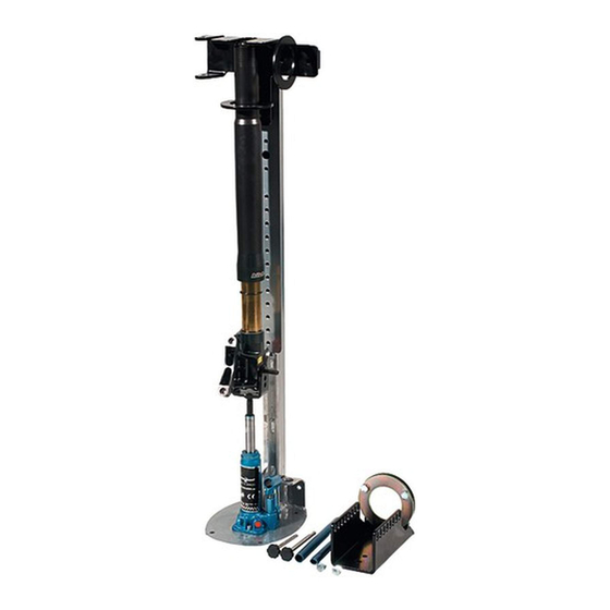
SA-07 Shock absorber dismantler
Bike- - - - Lift EUROPE s.r.l.
Bike
Bike
Bike
Lift EUROPE s.r.l.
Lift EUROPE s.r.l.
Lift EUROPE s.r.l.
via Don Milani, 40/42
43012 Sanguinaro di Fontanellato (PARMA) – Italy
Web site:
www.bikelifteurope.it
E-mail:
info@bikelifteurope.it
Operating manual No. 057-2-6-0009-R0
Version 2018
EN
Page 1
Advertisement
Table of Contents

Related Manuals for Bike-Lift SA-07


Summary of Contents for Bike-Lift SA-07
- Page 1 EC Use and Maintenance Manual SA-07 Shock absorber dismantler Bike Bike Bike Bike- - - - Lift EUROPE s.r.l. Lift EUROPE s.r.l. Lift EUROPE s.r.l. Lift EUROPE s.r.l. via Don Milani, 40/42 43012 Sanguinaro di Fontanellato (PARMA) – Italy Web site: www.bikelifteurope.it...
-
Page 2: Table Of Contents
Summary Information section ..........................4 Preface ..............................4 Prohibitions ............................5 Warranty ............................. 5 1.3.1 Warranty conditions ........................5 1.3.2 Insurance ............................ 5 Manufacturer identification ....................... 6 Technical assistance and spare parts ....................6 EC Declaration of conformity ......................7 Normative references ......................... - Page 3 Dismantling/scrapping section ......................18 Storage .............................. 18 Scrapping and disposal ........................18 Scrapping materials .......................... 18 Instructions for a suitable waste treatment ..................18 Electrical and electronic equipment waste ..................19 Operation section ..........................20 Use ..............................21 Maintenance section ........................23 Maintenance .............................
-
Page 4: Information Section
Information section Preface The EC Use and Maintenance Manual is a document issued by Bike-Lift Europe s.r.l. as an integral part of the Machine. The purpose of this publication is to provide the operator with efficient and safe instructions regarding the use and maintenance. -
Page 5: Prohibitions
It also becomes void if the product has been submitted to performances exceeding those indicated by Bike-Lift Europe s.r.l. 1.3.2 Insurance All Bike-Lift Europe s.r.l products are insured with an RCP policy with a price ceiling of € 3.000.000. Damages caused by negligence or tampering are excluded. Operating manual No. 057-2-6-0009-R0 Page 5... -
Page 6: Manufacturer Identification
CAUTION: THE RECIPIENT WILL BE CHARGED FOR THE REPLACEMENT TOGETHER WITH THE SHIPPING COSTS. We recommend that you always contact Bike-Lift Europe s.r.l. for all those Assistance and maintenance operations that are not described or indicated in this Manual. Operating manual No. 057-2-6-0009-R0... -
Page 7: Ec Declaration Of Conformity
Io sottoscritto Je soussigné The undersigned Unterzeichnete El abajo firmante Ondergetekende im name der Bike-Lift EUROPE s.r.l. via Don Milani, 40/42, 43012 Sanguinaro di Fontanellato (PARMA) – Italy Dichiara sotto la Déclare sous sa Declares under its Erklärt auf eigene... -
Page 8: Normative References
UNI 1285-68 pressure 1.8 General regulations and conventions This manual is an integral part of the product and MUST be kept for further reference. FOR ANY REQUEST FOR CLARIFICATION, CONTACT THE EMPLOYER OR THE BIKE-LIFT EUROPE S.R.L TECHNICAL SERVICE, AVOIDING PERSONAL INITIATIVES THAT COULD CAUSE VERY SERIOUS OR FATAL ACCIDENTS. -
Page 9: Key
1.9 Key SHOCK ABSORBER DISMANTLER: spring compression system for the replacement of shock absorbers and fork gaskets. OPERATOR: In compliance with Directive 2006/42/EC and subsequent updates, it is specified that the term "operator" means the person (s) in charge of installing, operating, adjusting and cleaning the machine. -
Page 10: Machine Description
Machine description 2.1 Machine name The Shock Absorber Dismantler described in this manual has been specifically designed for use in the dismantling and assembly operations of shock absorbers and gaskets for motorcycle forks. 2.2 Shock Absorber Dismantler identification The machine has an identification plate fixed in a visible way as indicated in the following picture. -
Page 11: Intended Use And Reasonably Foreseeable Misuse
Intended use and reasonably foreseeable misuse The shock absorber dismantler is intended exclusively for disassembly and/or assembly of shock absorbers and/or gaskets for motorcycle forks. The following operations are not permitted: • use for industrial shock absorbers is prohibited • use in potentially explosive atmospheres environments is forbidden •... -
Page 12: Safety Section
Safety section 3.1 Environmental working values The use environment of the machine must be well lit, must not present explosion hazards of any kind and must be protected from atmospheric precipitations. The machine works properly within the following values: • Ambient temperature between 5° and 40° C; •... -
Page 13: General Safety Rules
General safety rules • The shock absorber dismantler must only be operated by trained and authorized personnel. • Before using the shock absorber dismantler, check that it has not been damaged, that there are no air leaks or worn parts. •... -
Page 14: Transport And Handling Section
Transport and handling section Transport, handling and storage CAUTION: Disseminate the instructions described in this chapter to all personnel involved in the transport and handling of the machine. For safety reasons, the moving parts must be locked before transport. Unpacking If the machine is supplied wrapped in nylon cloth, any accessories, spare parts and consumables will be packed in cardboard boxes and positioned above the work surface. -
Page 15: Packaging And Transport
Packaging and transport You can manually handle the packaged machine, as previously described (see section 4.2), but it is recommended to use lifting means such as a pallet jack whose maximum lifting capacity must not be less than the total weight of the shock absorber dismantler. N.B. -
Page 16: Installation Section
Installation section The machine must be installed in compliance with the safety regulations and instructions included in this chapter. The machine must be positioned in such a way as to allow the Operator to easily replace the shock absorbers or the gaskets of the bike fork. The shock absorber dismantler must therefore be installed by taking into account the minimum distances from walls or other possible boundaries (boundaries are imaginary lines that delimit the work or safety areas of other machines or structures). -
Page 17: Filling
Filling N.B. When the oil level in the tank drops, generally following: volume absorption by the cylinder volume absorption by the system the discharge of air bubbles left in the pipes it is necessary to fill up the oil level by bringing it to the correct level and checking it with the level indicator. -
Page 18: Dismantling/Scrapping Section
Dismantling/scrapping section Storage In case of prolonged storage, protect the machine from rain and wind and possibly store it in a dry place. Protect the electrical parts from dust and external agents. The machine can be seriously damaged if, while pending for the installation, it is kept in a critical temperature environment. -
Page 19: Electrical And Electronic Equipment Waste
Electrical and electronic equipment waste According Legislative Decree no. 151 of 25 of July 2005, the Italian Government has implemented the European Parliament directives on the disposal of electrical and electronic equipment waste (WEEE) (Directive 2002/95/EC and 2003/108/EC). The decree specifically establishes measures and procedures aimed to: 1. -
Page 20: Operation Section
Operation section Before starting any maneuver, make sure that there are no other people in the immediate vicinity of the machine. Before starting to use the shock absorber dismantler, make sure that it has been well fixed to the ground using the four holes in the base of the structure (Figure 2-holes in the base of the structure) Check the correct operation of the shock absorber dismantler by carrying out a series of... -
Page 21: Use
7.1 Use Close the piston valve with one side of the pumping lever (Figure 3). Figure 3 piston valve closure Compress the spring until the spring lock (Figure 4) is released. Figure 4 spring compression Remove the spring lock and release the spring by unloading the piston with the pumping lever (Figure 5Errore. - Page 22 Extract the pin and remove the shock absorber (Figure Figure 6 pin extraction Released shock absorber (Figure 7). Figure 7 released shock absorber Reverse procedure for reassembly. WARNING: • Do not subject the shock absorber dismantler to overloads; always check the integrity of the machine.
-
Page 23: Maintenance Section
Maintenance section The maintenance operation is the absolute prerogative of professional operators and specialized technicians, in compliance with the requirements of Machinery Directive 2006/42/ EC and subsequent updates. Maintenance EMERGENCY MAINTENANCE OPERATIONS (REPAIRS) MUST BE CARRIED OUT BY THE MANUFACTURING COMPANY PERSONNEL AT THE CONSTRUCTION FACILITY OR BY SPECIALIZED AND PROPERLY TRAINED STAFF. -
Page 24: Problems And Remedies
8.3 Problems and remedies PROBLEM PROBABLE CAUSE REMEDY Make sure that the compressed Connect the machine to the The machine does not air connection has been carried local pneumatic network using work. out. the supplied quick coupling. The two spring pin arms Lubricate the sliding parts of Dust and dirt deposit along the do not slide smoothly on... -
Page 25: Technical Diagrams And Components Section
Technical diagrams and components section Operating manual No. 057-2-6-0009-R0 Page 25 Version 2018... -
Page 26: Machine Maintenance Sheet
Machine maintenance sheet Machine no.: description Serial number: Routine maintenance description and frequency Type of Intervention Next Date intervention Intervention description carried out intervention Notes (*) Intervention type key: R = routine/preventive E = emergency Operating manual No. 057-2-6-0009-R0 Page 26 Version 2018... - Page 27 NOTES ____________________________________________________________________________ ____________________________________________________________________________ ____________________________________________________________________________ ____________________________________________________________________________ ____________________________________________________________________________ ____________________________________________________________________________ ____________________________________________________________________________ ____________________________________________________________________________ ____________________________________________________________________________ ____________________________________________________________________________ ____________________________________________________________________________ ____________________________________________________________________________ ____________________________________________________________________________ ____________________________________________________________________________ ____________________________________________________________________________ ____________________________________________________________________________ ____________________________________________________________________________ ____________________________________________________________________________ ____________________________________________________________________________ ____________________________________________________________________________ ____________________________________________________________________________ ____________________________________________________________________________ ____________________________________________________________________________ ____________________________________________________________________________ ____________________________________________________________________________ ____________________________________________________________________________ ____________________________________________________________________________ ____________________________________________________________________________ ____________________________________________________________________________ ____________________________________________________________________________ ____________________________________________________________________________ ____________________________________________________________________________ ____________________________________________________________________________ ____________________________________________________________________________ ____________________________________________________________________________ ____________________________________________________________________________ ____________________________________________________________________________ ____________________________________________________________________________ ____________________________________________________________________________ ____________________________________________________________________________ ____________________________________________________________________________ ____________________________________________________________________________...
- Page 28 NOTES ____________________________________________________________________________ ____________________________________________________________________________ ____________________________________________________________________________ ____________________________________________________________________________ ____________________________________________________________________________ ____________________________________________________________________________ ____________________________________________________________________________ ____________________________________________________________________________ ____________________________________________________________________________ ____________________________________________________________________________ ____________________________________________________________________________ ____________________________________________________________________________ ____________________________________________________________________________ ____________________________________________________________________________ ____________________________________________________________________________ ____________________________________________________________________________ ____________________________________________________________________________ ____________________________________________________________________________ ____________________________________________________________________________ ____________________________________________________________________________ ____________________________________________________________________________ ____________________________________________________________________________ ____________________________________________________________________________ ____________________________________________________________________________ ____________________________________________________________________________ ____________________________________________________________________________ ____________________________________________________________________________ ____________________________________________________________________________ ____________________________________________________________________________ ____________________________________________________________________________ ____________________________________________________________________________ ____________________________________________________________________________ ____________________________________________________________________________ ____________________________________________________________________________ ____________________________________________________________________________ ____________________________________________________________________________ ____________________________________________________________________________ ____________________________________________________________________________ ____________________________________________________________________________ ____________________________________________________________________________ ____________________________________________________________________________ ____________________________________________________________________________...
Need help?
Do you have a question about the SA-07 and is the answer not in the manual?
Questions and answers