Table of Contents
Advertisement
Quick Links
Advertisement
Table of Contents

Related Manuals for Weidmüller WCU 650


Summarization of Contents
About this documentation
Scope
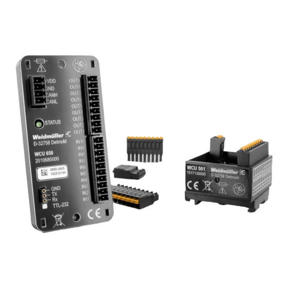
Manual describes the WCU 501 and WCU 650 logic units and provides an introduction to programming.
Symbols and notes
Explains safety notices and warning symbols like Danger, Warning, Caution, and Attention used in the manual.
Complete documentation
Mentions quick start guide and availability on the Weidmüller website.
Safety
General safety notice
Instructions on always disconnecting power, securing the system, and following national/international laws.
Intended use
Describes the logic units as controllers for industrial environments, not for life-preserving or hazardous applications.
Device description
Assembly and installation
Details the WCU 501 and WCU 650 units, including graphical programming, digital inputs, outputs, and CAN interface.
Installation connections
Explains the wiring connections for WCU 650, detailing pin assignments and functions for various terminals.
Mounting and installation
Mounting the device
Provides instructions for mounting the WCU 501 and WCU 650 units on TS35 terminal rails or using drill holes.
Installing the connections
Guides on connecting wires using ferrules, connecting to PC via USB, and ensuring correct polarity and external fuse.
Commissioning
Installing the software
Details system requirements and steps to download and install the miCon-L programming software and USB driver.
Connecting the PC
Explains how to connect the WCU 501 and WCU 650 to a PC via USB or RS232 for programming.
Starting the program
Guides on launching the miCon-L software, configuring serial interfaces, and selecting the correct port.
Configuration
Creating a project
Describes how to create a new project in the miCon-L software, selecting the correct control unit and project location.
Operating the programming interface
Explains the layout of the miCon-L programming interface, including project tree, current selection, and function blocks.
Function block library
Details how to access and use the function block library within the miCon-L programming interface.
Simulation
Explains how to simulate the program for functionality and error checking without connecting to the logic unit.
Loading program to the logic unit
Guides on transferring a new or changed program to the logic unit via USB connection.
Online observation
Explains how to connect the logic unit to the PC and perform online observation of the program's execution.
Example project
Presents an example project demonstrating the creation of a building automation logic unit for a water tank and ventilation unit.
Technical Data
General data
Provides general specifications for WCU 501 and WCU 650, including connection type, operating voltage, and interface.
Analogue inputs
Details specifications for analogue inputs, including number, pin assignment, resolution, input voltage, and resistance.
Digital inputs
Lists specifications for digital inputs, including number, pin assignment, input frequency, voltage, resistance, and pulse length.
Digital outputs
Details specifications for digital outputs, including number, pin assignment, output voltage, current, and switching frequency.
PWM output
Specifies parameters for PWM output, including number and type of output.
CAN interface
Provides technical data for the CAN interface, including baud rate, bus system, and identifier.
Dimensions and weight
Lists the physical dimensions (height, width, depth) and weight of the WCU 501 and WCU 650 units.
Ordering data
Ordering data
Presents ordering information including order number, part designation, and description for WCU 501 and WCU 650 units and accessories.
Need help?
Do you have a question about the WCU 650 and is the answer not in the manual?
Questions and answers